
Static Fluid Mixer and Method

a technology of mixer and fluid, applied in the direction of mixing, transportation and packaging, chemical instruments and processes, etc., can solve the problems of inability the output mixture may still lack the desired level of homogeneity, and the static mixer lacks the capability to completely subdivide the added input fluid, etc., to achieve effective mixing, reduce the amount of energy, and reduce the effect of pressure drop

Inactive Publication Date: 2013-01-24
DOOLIN MICHAEL B +1
View PDF10 Cites 31 Cited by
  • Summary
  • Abstract
  • Description
  • Claims
  • Application Information

AI Technical Summary

Benefits of technology

This patent describes a static mixer that uses special mixing elements to create a very homogeneous output fluid mixture. The mixer can be used with different adding fluids and carrier fluids, and it requires less energy and requires less equipment, resulting in lower costs. The size and efficiency of the mixer make it useful in various applications and easy to install. The mixer achieves effective mixing by inducing turbulence in the fluids, which results in a more homogeneous output fluid mixture. The structural mixing elements have a compact size and can be used in various applications.

Problems solved by technology

The turbulence results principally from pressurized and energized interaction of the fluid with the structural mixing elements as the fluid is forced through the static mixer.
Even though the clumps of powdered grains, or the large bubbles, or the large drops, may be uniformly mixed with the carrier fluid, the output mixture may still lack the desired level of homogeneity, because the clumps, bubbles and drops have not been subdivided into smaller parts.
Under such circumstances, the static mixer lacks the capability to completely subdivide the added input fluid, although the larger clumps, bubbles and drops may be uniformly distributed within the output fluid.
For example, in the case where the added input fluid is a particular chemical which is used to coat an object for some beneficial purpose, if the added input chemical has not been subdivided into very small volumetric quantities, the coating of the object will not be uniform because the clumps, large drops or large bubbles will create a non-uniform distribution when they interact with the object.
Under such circumstances, a greater amount of the added input chemical will usually be required to coat the object adequately, due to the non-uniformity of the volumetric quantities of the added input fluid in the carrier fluid.
This situation usually results in a higher cost of application, because more of the added input chemical is required than would otherwise be the case with a more thorough distribution of uniformly and finely subdivided volumetric quantities of the added input fluid in the carrier fluid.
The effectiveness of the static mixer therefore directly affects the cost of use.
Because the static mixer consumes energy from the pressurized carrier fluid to obtain the energy for mixing the added fluid with the carrier fluid, pressure and energy is lost within the static mixer to achieve the mixing effect.
Many applications for static mixers do not permit relatively large physical size devices to be used because of space constraints.
Large static mixers can generally achieve more thorough mixing by adding more structural mixing elements, thereby increasing the overall physical size of the static mixer, and increasing the amount of energy consumed in achieving the level of mixing.
The increased size and the number of structural mixing elements adds to the cost of the mixer, and may require the larger pumps and motors to supply more energy to the carrier fluid in order to achieve thorough mixing.
Inefficient static mixers which consume additional energy by creating high pressure drops cost more money to operate because the pumps which supply the carrier fluid must be larger and must use more energy to create sufficient pressure in the output fluid flow to achieve the purposes to which that output fluid flow is to be put.
The pumps and related hardware must be constructed to withstand higher pressures and higher capacities, which add to the cost of the entire mixing system.
Under such circumstances, a single type of static mixer may not achieve a universal and desired level of effectiveness in mixing a variety of different added input fluids and carrier fluids.

Method used


Image

  • Static Fluid Mixer and Method
  • Static Fluid Mixer and Method
  • Static Fluid Mixer and Method

Examples


Embodiment Construction

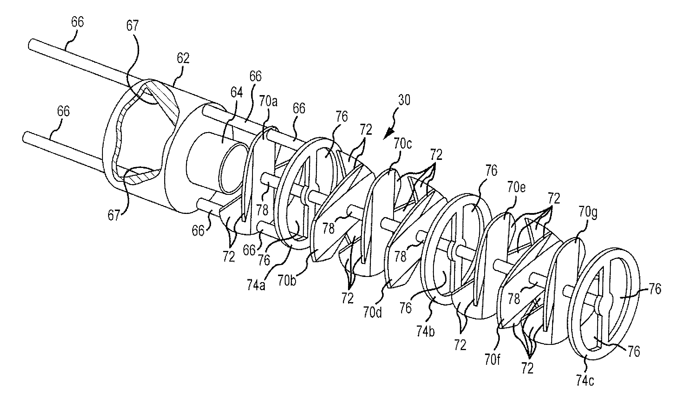
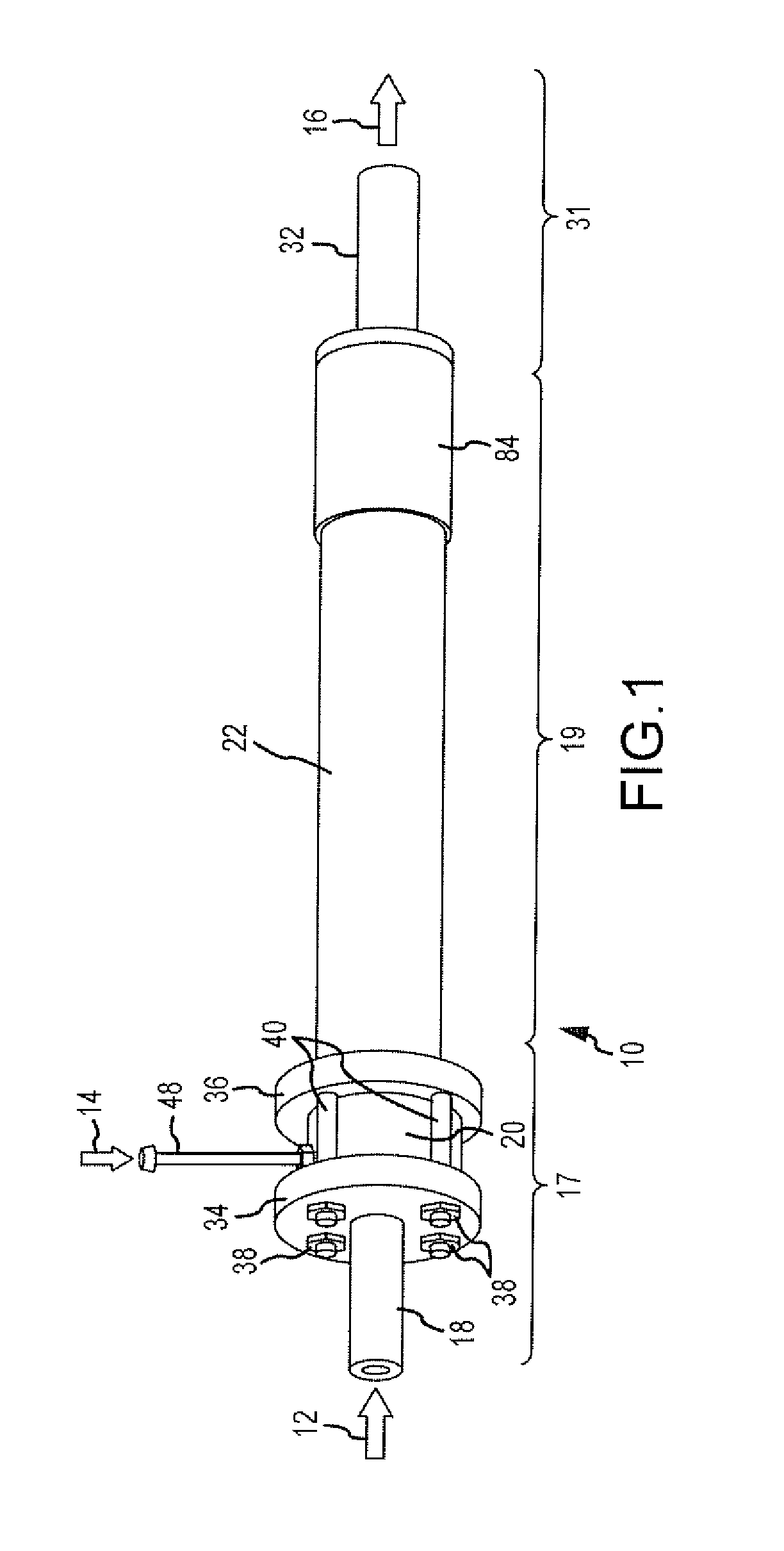
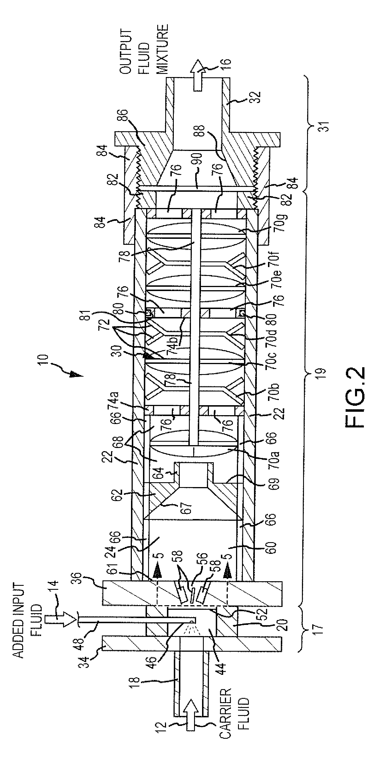
[0037]A static mixer 10 which embodies the present invention is shown in FIGS. 1 and 2. The static mixer 10 mixes an input carrier fluid 12 with a relatively smaller amount of an added input fluid 14 to achieve an output fluid mixture 16 which is a substantially homogeneous dispersal of very finely subdivided volumetric quantities (powder grains, drops or bubbles) of the added input fluid 14 dispersed throughout the carrier fluid 12. The static mixer 10 is a continuous flow type mixer in which the carrier fluid 12 and the added input fluid 14 are continuously supplied to static mixer 10 to create the output fluid mixture 16. Typically, the carrier fluid 12 will have a much higher volumetric flow rate than the added input fluid 14, although the static mixer 10 will also accommodate comparable volumetric flows of the carrier fluid 12 and the added input fluid 14. The carrier fluid 12 and the added input fluid 14 are pressurized by pumps (not shown) before delivery into the static mixe...


PUM

PropertyMeasurementUnit
Pressureaaaaaaaaaa
Angleaaaaaaaaaa
Flow rateaaaaaaaaaa

Abstract

A carrier fluid and an added input fluid are mixed together in a static mixer to create an emulsified output fluid mixture. The static mixer comprises a plurality of mixing chambers whose cross-sectional size expand considerably relative to an inlet, a series of bent and curved baffle plates which divert, rotate, divide, reverse and otherwise create turbulence in the combined flow, and inlet chamber in which the added input fluid is dispensed upstream into the carrier fluid, and a number of other structural mixing elements which, through turbulence, abrupt pressure drops and velocity changes, subdivide the added input mixture into very small volumetric quantities evenly dispersed within the carrier fluid to create a homogeneous output fluid mixture.

Description

[0001]This invention relates to static mixing, and more particularly to a new and improved static mixer and method for continuously mixing, dispersing or emulsifying two or more different input fluid substances which are usually not soluble or chemically combinable with one another, to create a single highly-homogeneous output fluid mixture of the multiple fluid substances.BACKGROUND OF THE INVENTION[0002]A static mixer is a device which does not require an external motor and mixing paddles or stirrers to mix or combine different substances. In most cases, the static mixer has no moving parts. Instead, the static mixer uses one or more stationary structural mixing elements which cause the fluid passing through the static mixer to experience abrupt variations in velocity and pressure. The variations in velocity and pressure create turbulence in the fluid. The turbulent fluid creates shear forces which disperse and distribute volumetric quantities of one of the input fluid substances,...

Claims


Application Information

Patent Timeline
IPC IPC(8): B01F5/06B01F15/02
CPCB01F5/0415B01F5/0428B01F5/0451B01F5/0617B01F2005/0637B01F15/00928B01F3/0807B01F3/12B01F2005/0034B01F5/0688B01F23/41B01F23/50B01F2025/918B01F25/3121B01F25/31242B01F25/3131B01F25/43151B01F25/431972B01F25/4521B01F35/56
Inventor DOOLIN, MICHAEL B.BERINGER, BARRY M.
Owner DOOLIN MICHAEL B
Learn More