Eureka AIR delivers breakthrough ideas for toughest innovation challenges, trusted by R&D personnel around the world.

Wireless Network System, Method of Controlling the System, and Wireless Network Relay Device

a wireless network and relay device technology, applied in repeater circuits, line-transmission details, wireless commuication services, etc., can solve the problems of home or similar location not being able to connect wirelessly to a router device configured, etc., to suppress the production cost of the wireless network relay device and reduce work load

Inactive Publication Date: 2013-01-17
BUFFALO CORP LTD
View PDF6 Cites 16 Cited by
  • Summary
  • Abstract
  • Description
  • Claims
  • Application Information

AI Technical Summary

Benefits of technology

The wireless network relay device described in this patent can communicate with different devices to facilitate wireless connections. The device does not need to set up the wireless communication setup information, which can be pre-set and automatically sent to the relay device, reducing the workload for users. This also eliminates the need for display or input means on the relay device, reducing production costs. Overall, this device provides greater access to wireless networks and improves user experience.

Problems solved by technology

A consequent problem has been that a client on the move from an outside destination to a home or similar location cannot connect wirelessly to a router device configured as it is.
For similar reasons, a problem for a client having been connected to the Internet or other network via a wireless router at a home or similar location has been not being able, in a site away from the home or similar location, to wirelessly connect to a mobile access point configured as it is.
Furthermore, these problems are not limited to wireless routers, and may occur in situations where a Layer-3 switch or any given similar wireless network relay device having a wireless communications function is set up (i.e., stationarily disposed).

Method used


Image

  • Wireless Network System, Method of Controlling the System, and Wireless Network Relay Device
  • Wireless Network System, Method of Controlling the System, and Wireless Network Relay Device
  • Wireless Network System, Method of Controlling the System, and Wireless Network Relay Device

Examples


first embodiment

A. First Embodiment

[0066]A1. System Configuration

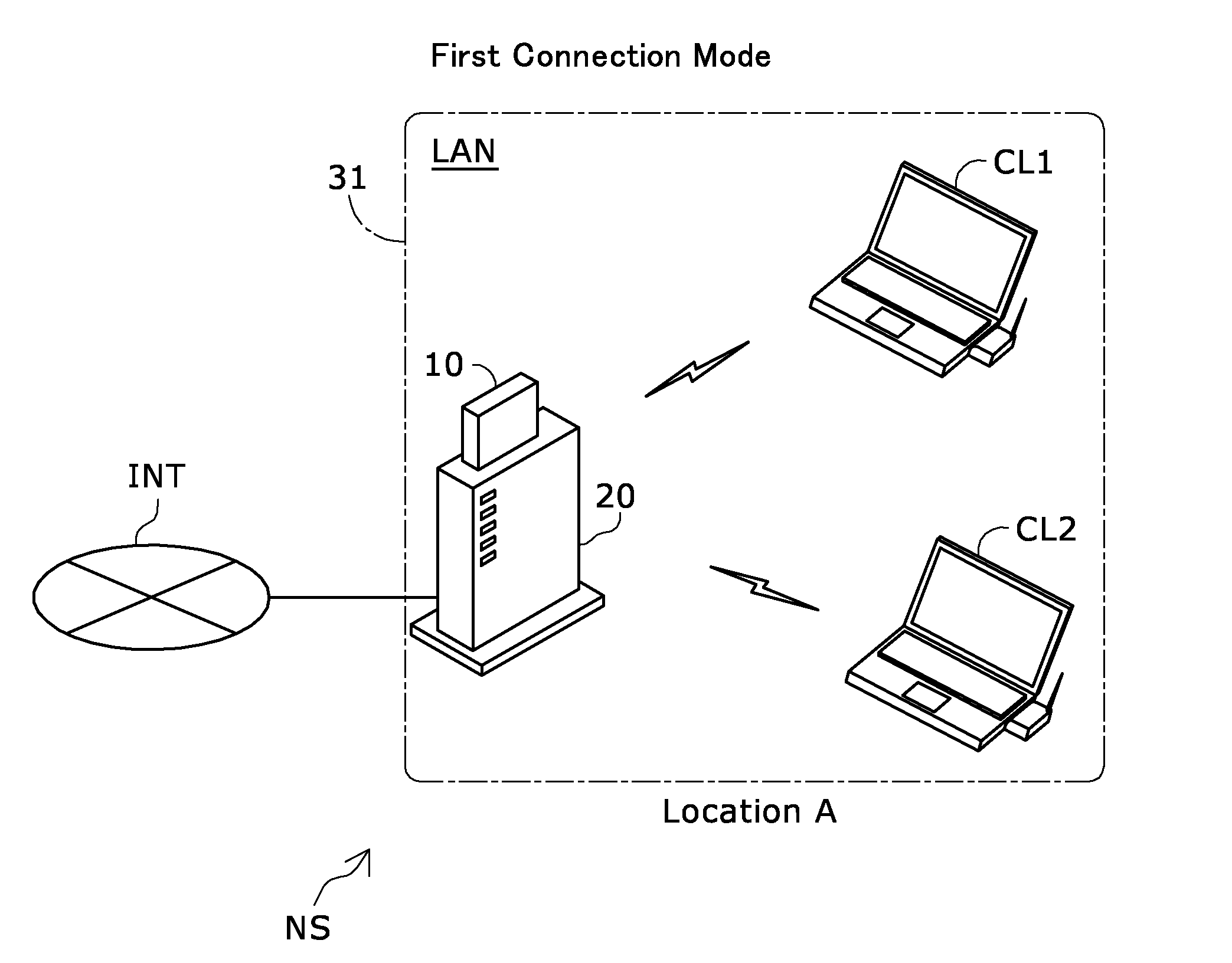
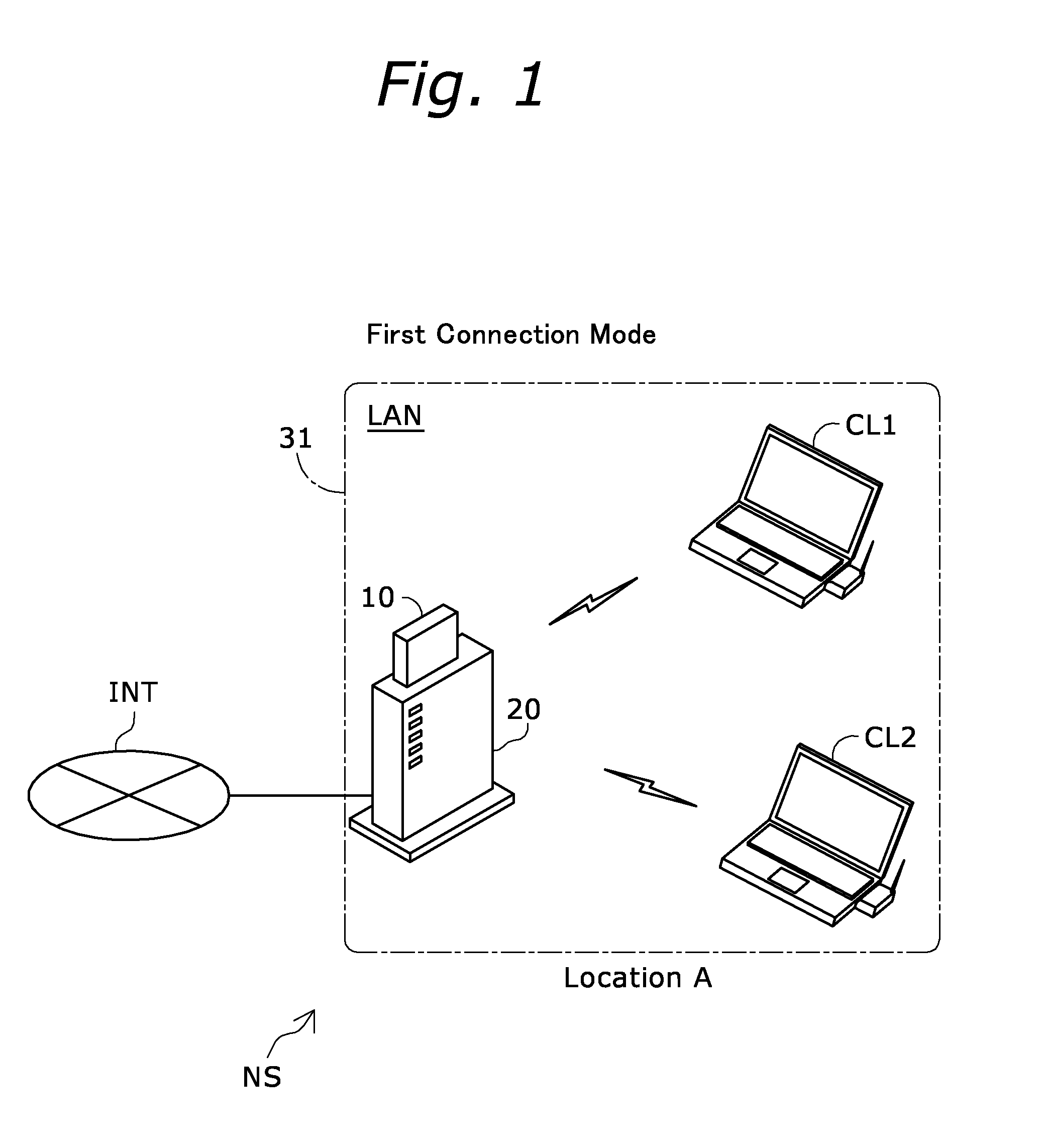
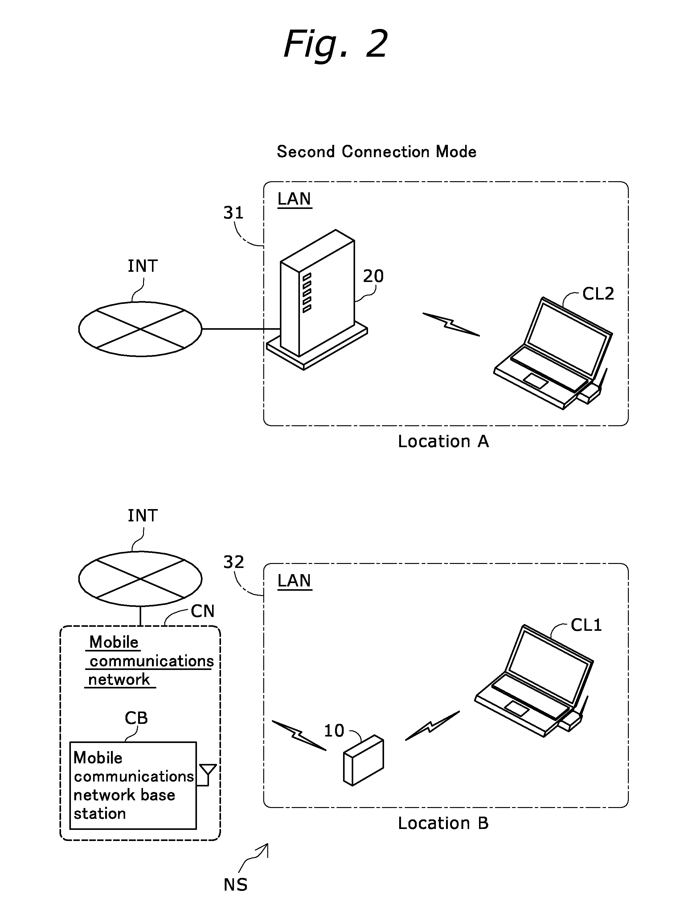
[0067]Reference is made to FIG. 1, a simplified explanatory diagram illustrating the configuration of a wireless network system according to a first embodiment of the present invention. A wireless network system NS includes a home gateway 20, and a portable access point 10. The wireless network system NS is a system for connecting clients CL1 and CL2 to the Internet INT. The wireless network system NS assumes a plurality of connection modes relating to the home gateway 20 and portable access point 10. In the connection mode represented in FIG. 1 (first connection mode) the home gateway 20 is connected to the Internet INT via an access line (e.g., an optical line or an asymmetric digital subscriber line (ADSL), not shown). The portable access point 10 is physically connected to (in contact with) the home gateway 20. It should be understood that the two clients CL1 and CL2 are connected to the home gateway 20 by way of wireless communic...

second embodiment

B. Second Embodiment

[0108]Reference is made to FIG. 9, a sequence chart representing procedural flows in a setup updating process executed in a wireless network system of a second embodiment. Referring to FIG. 9, the left side and the right side are respectively the same as the left side and right side of the sequence chart of the first embodiment shown in FIG. 5, and therefore the description is not provided herein.

[0109]The wireless network system of the second embodiment is different from the wireless network system NS of the first embodiment in points as follows: one, the setup information transmission control unit 214 of the home gateway 20 does not support the multiple SSID; two, addition of a step S112 as a procedure at the portable access point 10 in the setup updating process; and three, execution of a step S225a, in place of the steps S225 and S230, as a procedure at the home gateway 20 in the setup updating process. Otherwise, the configuration of the wireless network sys...

third embodiment

C. Third Embodiment

[0116]Reference is made to FIG. 12, a simplified explanatory diagram illustrating the configuration of a wireless network system of a third embodiment. FIG. 12 shows a first connection mode of a wireless network system NSa of the third embodiment. The wireless network system NSa of the third embodiment is different from the wireless network system NS of the first embodiment shown in FIG. 1, where the former has the portable access point 10 connected to a home gateway 20a via a cradle 40. Otherwise the configuration of the wireless network system NSa is the same as that of the wireless network system NS of the first embodiment. The cradle 40 is connected to the home gateway 20a by way of a network cable Ca1. When the cradle 40 is physically connected to the portable access point 10 via a contact, the cradle 40 supplies the portable access point 10 with power and mediates data exchange between the portable access point 10 and the home gateway 20a.

[0117]Reference is...


PUM


Abstract

A wireless network system includes first and second network relay devices, with the first relay device having first wireless communication setup information pre-set thereto and including a first communication I / F part and a first wireless communication setup information transmission part for sending first wireless communication setup information to the second wireless relay device if the first and second relay devices are enabled to communicate with each other, and with the second relay device including: a second communication I / F part; a first wireless communication setup information reception part for receiving the first wireless communication setup information via the second communication I / F part; and a first wireless communication part for performing wireless communication with a client by using the received first wireless communication setup information.

Description

BACKGROUND OF THE INVENTION[0001]1. Technical Field[0002]The present invention relates to configuring information used in wireless communications.[0003]2. Description of the Related Art[0004]Technology whereby a transmission control protocol (TCP) / internet protocol (IP) session is established between a wireless local area network (LAN) access point (also referred to simply as “access point” hereinafter) arranged in a home, office, etc., and an access point arranged in a site away from the home or similar location, to continue communications in the event the wireless LAN environment of a personal computer or other wireless LAN client device (also referred to simply as “client” hereinafter) changes has been proposed. (Reference is made to Japanese Unexamined Patent App. Pub. No. 2009-284114.)[0005]The above-described technology for establishing a TCP / IP session between an access point in a home or similar location, and an access point in a site away from the home or similar location, ...

Claims


Application Information

Patent Timeline
Patent Type & Authority Applications(United States)
IPC IPC(8): H04W92/04H04W16/00H04W12/06H04W12/08
CPCH04W48/16H04W84/047H04W92/04H04W88/10H04W84/12
Inventor HABA, YOSHIFUMI
Owner BUFFALO CORP LTD
Why Eureka
Eureka Blog
Learn More