
Induction heating system employing induction-heated switched-circuit vessels

a switched-circuit vessel and induction heating technology, applied in induction heating, cooking vessel materials, kitchen equipment, etc., can solve the problems of complex energy inefficiency, large unit energy input, and a number of deficiencies in the conventional steam tabl

Active Publication Date: 2013-01-17
TSI TECH
View PDF8 Cites 20 Cited by
  • Summary
  • Abstract
  • Description
  • Claims
  • Application Information

AI Technical Summary

Benefits of technology

The patent describes a device that has different zones that can apply different levels of heat to different parts of the body using an alternating magnetic field. The device has a coil that produces Joule heating, which can provide precise heating to specific areas. This technology can improve the efficiency and accuracy of heating for therapeutic purposes.

Problems solved by technology

However, conventional steam tables suffer from a number of deficiencies.
First, these units require considerable energy inputs to create and maintain the heating steam.
This energy inefficiency is compounded because of the fact that the HVAC systems of the buildings housing the steam tables must be operated to counteract the heat and humidity generated by the steam tables.
Furthermore, the steam tables containing warm / hot water can be contaminated with undesirable microorganisms which can in turn contaminate the food being served.
However, there is no means of differentially heating different portions of the stainless steel food-holding pans, i.e., the entirety of the pans is heated by appropriately positioned induction work coils.
Thus, while induction heating of pans is well known, a number of problems remain.
Most importantly, prior induction heating systems have not provided effective means for differentially heating respective portions of a pan or vessel to different temperatures or over different time periods.

Method used


Image

  • Induction heating system employing induction-heated switched-circuit vessels
  • Induction heating system employing induction-heated switched-circuit vessels
  • Induction heating system employing induction-heated switched-circuit vessels

Examples


embodiment 1 (fig.4)

Embodiment 1 (FIG. 4)

Susceptor Coil Having Multiple Joule Heating Zones Providing Variable Watt Density Joule Heating Owing to Variable Trace Thicknesses, a Single Thermal Switch, and Thin Disk Eddy Current Thermometer Sensors

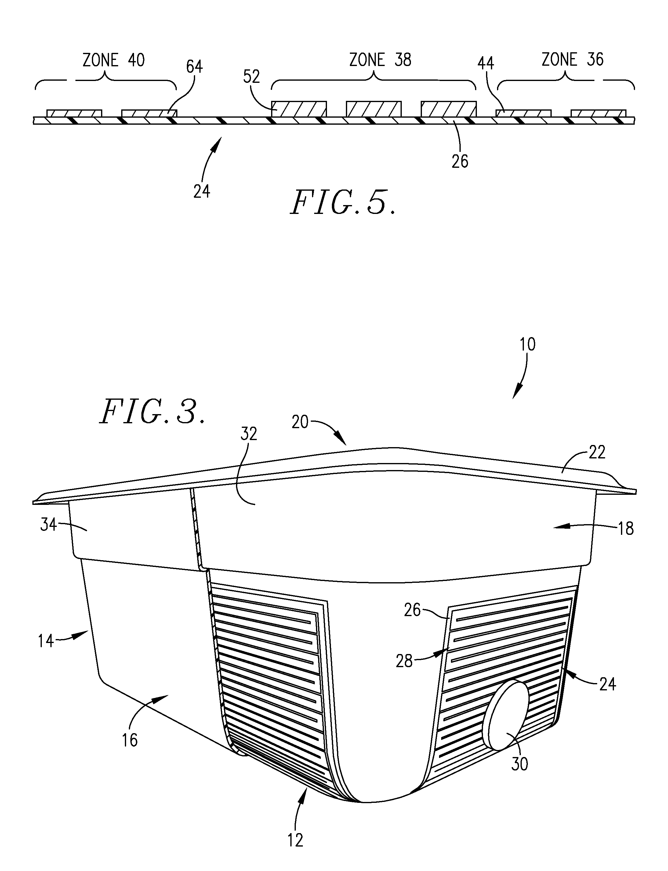
[0033]The susceptor coil 24 of FIG. 4 includes a thin synthetic resin base sheet 26 having the traces 28 printed on the upper face thereof. In the illustrated embodiment, the traces 28 are continuous and formed of copper, but other electrically conductive materials such as silver or carbon ink may also be used. This embodiment primarily relies upon variations in trace thickness to give the desired variable Watt density Joule heating of the coil 24 and hence the pan 10.

[0034]Referring in detail to FIG. 4, the coil 24 has a central zone 36, which when applied is adjacent bottom wall 12 of pan 10; a peripheral zone 38 surrounding the zone 36 and which when applied is adjacent the edge or transition between bottom wall 12 and sidewall structure 14; opposed end wall...

embodiment 2 (fig.6)

Embodiment 2 (FIG. 6)

Susceptor Coil Having Multiple Joule Heating Zones Providing Variable Watt Density Joule Heating Owing to Variable Trace Widths and Multiple Thermal Switches

[0050]FIG. 6 depicts another susceptor coil 90 also intended for use on a one-quarter size pan of the type illustrated in FIG. 3. Again, the coil 90 comprises a thin synthetic resin backing sheet 92 and a series of traces imprinted thereon broadly referred to by the numeral 94. As in the case of coil 24, the coil 90 presents a series of zones having different Joule heating characteristics, namely: a bottom zone 96 for application to the bottom wall 12 of pan 10; a peripheral zone 98 surrounding the zone 96 for application adjacent the edge or transition between bottom wall 12 and sidewall structure 14 of pan 10; opposed, outwardly extending end wall zones 100 and 102 for application to the end walls 18 of pan 10; and opposed, outwardly extending sidewall zones 104, 106 for application to the sidewalls 16 of ...

embodiment 3 (fig.7)

Embodiment 3 (FIG. 7)

Double Module Susceptor Coil for One-Half Size Pan

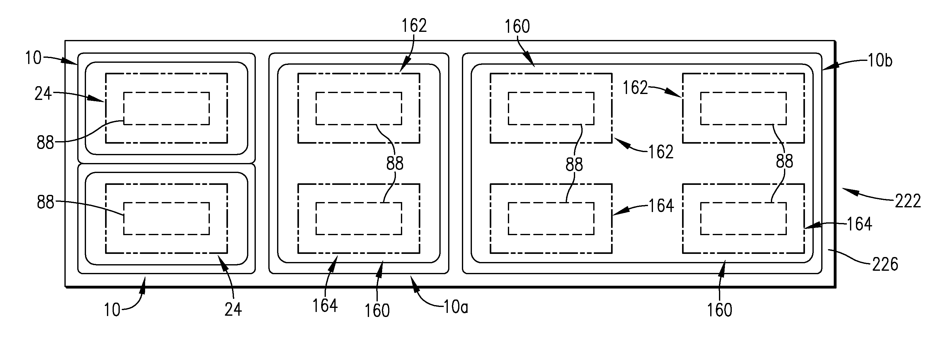
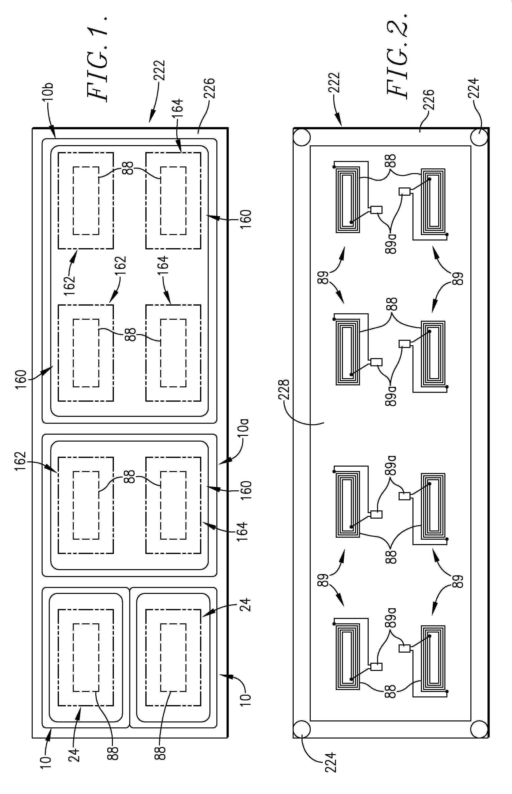
[0063]FIG. 7 illustrates a two-component induction heating coil assembly 160 intended for use on a synthetic resin, one-half size pan 10a, illustrated in FIG. 1. The coil 160 is made up of two identical, mirror image coils 162 and 164, which are imprinted upon a unitary synthetic resin backing sheet 165. The coils 162, 164 are electrically isolated from each and are designed to operate, with respect to a given work coil 88, in a manner identical to that of the coil for a one-quarter size pan. Given the identical nature of the coils 162, 164, only coil 162 will be described in detail.

[0064]Specifically, the coil 162 includes a primary bottom zone 166 comprising traces 168, and a peripheral zone 170 surrounding the zone 166 and made up of traces 172; the traces 168 begin at point 173 and connect with the traces 172 at point 174. As in the case of the previous embodiments, the traces 168 and 172 define respective, n...


PUM


Abstract

An induction heatable article such as a pan is provided having a synthetic resin body with at least one susceptor coil secured to the body and operable under the influence of an induction field to generate Joule heating within the coil to thereby heat the body. The coil has a plurality of zones, each adjacent a different portion of the body and capable of providing respective, different magnitudes of Joule heating-derived energy per unit time in the zones. A multiple-pan, modular food heating / warming table includes a table supporting an array of individually controllable induction heaters with a plurality of synthetic resin, food-holding pans positionable on the table, wherein each pan has a zoned susceptor coil for induction heating of the pans

Description

CROSS-REFERENCE TO RELATED APPLICATION[0001]This application claims the benefit of provisional application entitled INDUCTION HEATING SYSTEM EMPLOYING INDUCTION-HEATED SWITCHED-CIRCUIT VESSELS WITH EDDY CURRENT THERMOMETER TEMPERATURE CONTROL, Ser. No. 61 / 572,265, filed Jul. 14, 2011, and a second identically titled provisional application, Ser. No. ______, filed Jun. 25, 2012, both incorporated herein by reference in their entireties.BACKGROUND OF THE INVENTION[0002]1. Field of the Invention[0003]The present invention is broadly concerned with improved induction heatable articles, such as food-heating pans, which are designed to permit differential magnetic induction Joule heating of respective portions of the articles. More particularly, the invention is concerned with such articles, induction heating assemblies making use of the articles, and corresponding methods. Preferably, the induction heatable articles are formed of synthetic resin material and include one or more susceptor...

Claims


Application Information

Patent Timeline
IPC IPC(8): H05B6/12
CPCA47J36/027A47J36/02
Inventor CLOTHIER, BRIAN L.
Owner TSI TECH
Learn More