
Electrical switch with shear force contact weld release

a technology of contact weld release and electric switch, which is applied in the direction of contact-welding prevention/breaking, electrical apparatus, snap-action arrangements, etc., to achieve the effect of reducing the need, reducing the need, and resisting contact welding

Active Publication Date: 2013-01-17
ILLINOIS TOOL WORKS INC
View PDF3 Cites 14 Cited by
  • Summary
  • Abstract
  • Description
  • Claims
  • Application Information

AI Technical Summary

Benefits of technology

The present invention provides a switch that can control high amperage loads in an appliance and is designed to resist contact welding. The switch includes normally stationary contacts that are flexibly mounted, allowing them to move and separate from each other when contact welding occurs. This separation action generates a strong shear force across the contacts, which prevents the weld from breaking. The switch also includes a flexible metal strip that resiliently follows the second contact and provides resistance to the second lever. This design ensures that a high mechanical advantage acts on the over-center spring force to produce a shear force, without the need for increasing the strength of the spring or the actuation force of the switch. Additionally, this design prevents the weld-separating forces from being dissipated in flexure of the levers. By generating the shear force along the lever extensions, compressive or tensile forces are primarily generated in lieu of bending forces. Overall, this switch design offers improved performance and durability for controlling high amperage loads in an appliance.

Problems solved by technology

When contact welding occurs, unison movement of the welded contacts on their support arms induces a strong shear force across the face of the contacts tending to break any welds.

Method used


Image

  • Electrical switch with shear force contact weld release
  • Electrical switch with shear force contact weld release
  • Electrical switch with shear force contact weld release

Examples


Embodiment Construction

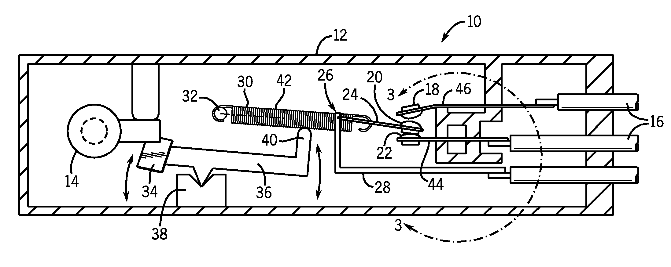
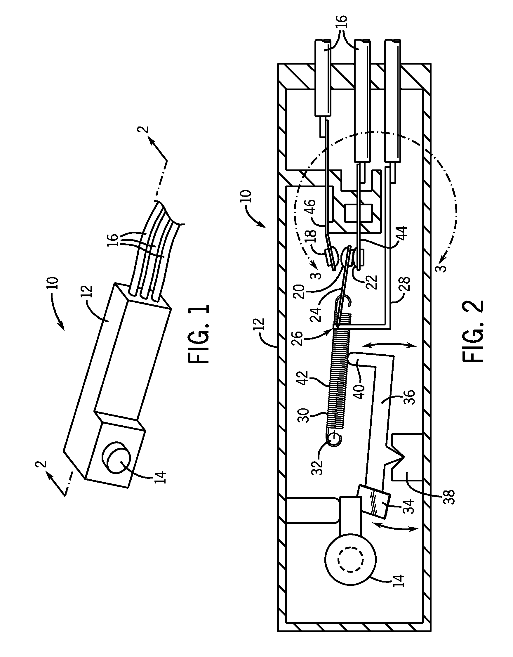
[0028]Referring now to FIG. 1, an electrical switch 10 per the present invention may provide for a housing 12, for example, of an insulating thermoplastic material. The housing 12 may expose therethrough a pushbutton operator 14 that may be pressed inward toward the housing 12 to activate an internal set of contacts to be described. Conductive leads 16 may extend from the housing 12 to communicate with external electrical circuits, for example motors or actuators of a household appliance (not shown).

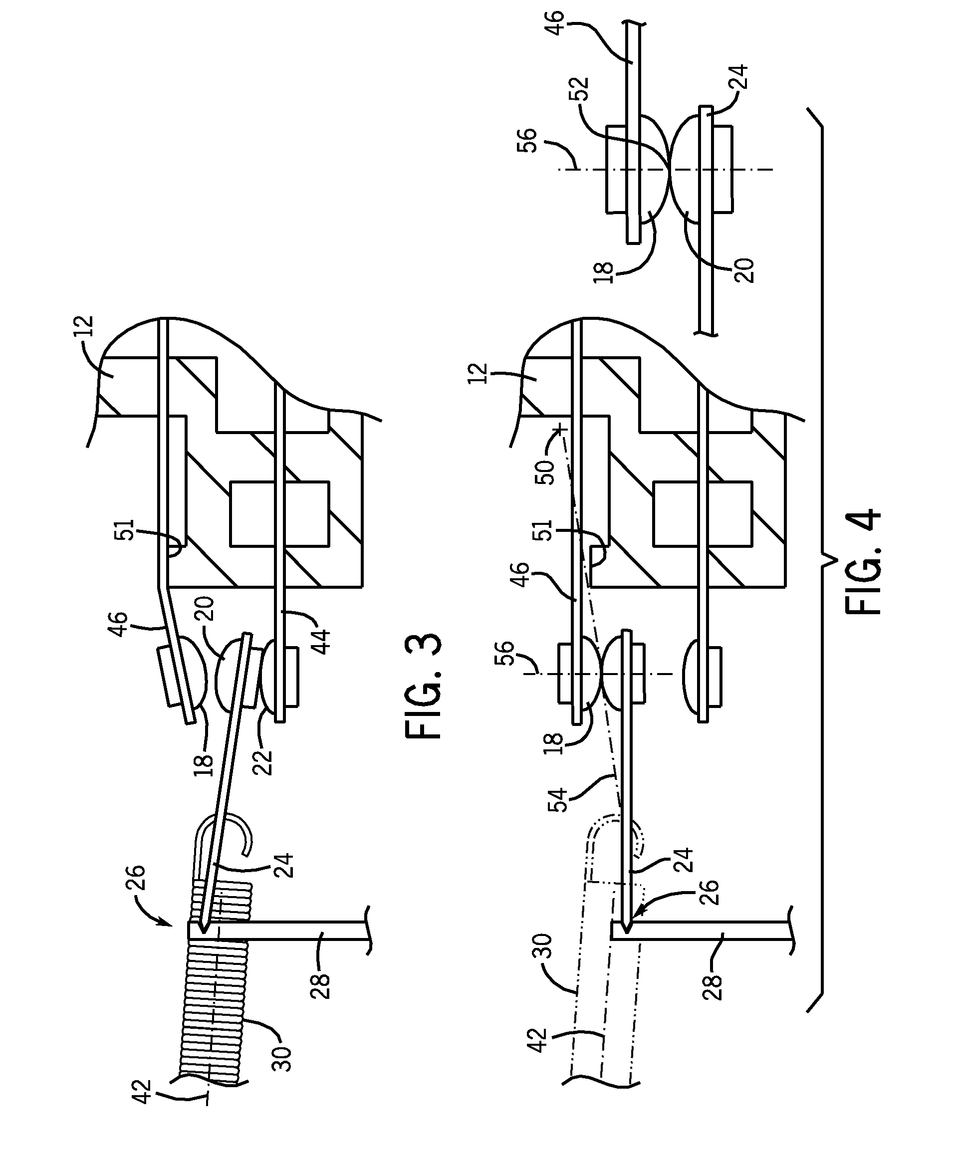
[0029]Referring now to FIG. 2, the electrical switch 10 may contain an upper contact 18, a center contact 20, and lower contact 22 arranged to provide a single pole, double throw electrical switch with the upper contact 18 and lower contact 22 generally flanking the center contact 20. The center contact 20 may move between the upper contact 18 and lower contact 20 to selectively and alternatively connect to only one of the upper contact 18 and lower contact 22.

[0030]The center contact 20...


PUM


Abstract

An electrical switch provides a center contact moving between two outer contacts, at least one of which is mounted on a lever. In the event of a contact weld forming between the center contact and the lever mounted contact, unison motion of the lever mounted contact following the center contact during switching causes a strong shear force tending to break the weld. In one embodiment, a fulcrum wall striking the lever of the lever mounted contact causes increased angulation between the contacts so that unison motion rotates and peels the contacts apart.

Description

CROSS-REFERENCE TO RELATED APPLICATIONS[0001]This application claims the benefit of U.S. provisional application No. 61 / 506,869 filed Jul. 12, 2011 hereby incorporated by reference in its entiretyFIELD OF THE INVENTION[0002]The present invention relates to an electrical switch and in particular to an electrical switch for providing a mechanism to break contact welds caused by current surges.BACKGROUND OF THE INVENTION[0003]Modern appliances such as washing machines and dryers may provide for lid or door switches detecting when the appliance lid or door is open. In many cases, these lid switches serve to help protect the consumer from machinery moving inside the appliance by turning off an appliance motor or otherwise deactivating moving elements of the appliance. Such switches may include a stationary contact disconnecting from a movable contact driven by movement of a switch operator when the lid or door is open. The two contacts may control power to a motor or brake or the like.[0...

Claims


Application Information

Patent Timeline
Patent Type & Authority Applications(United States)
IPC IPC(8): H01H21/24
CPCH01H1/16H01H13/28H01H2300/046H01H5/08H01H3/001
Inventor TENGLER, ADRIAN J.OSVATIC, MICHAEL S.HINTZ, MICHAEL K
Owner ILLINOIS TOOL WORKS INC
Learn More