Differential vector storage for non-volatile memory

Active Publication Date: 2013-01-10
KANDOU LABS
View PDF5 Cites 82 Cited by
  • Summary
  • Abstract
  • Description
  • Claims
  • Application Information

AI Technical Summary

Benefits of technology

The patent describes a way to store information in a non-volatile memory system using differential charging levels instead of absolute values. This approach allows for multiple rewriting of a single cell before a block erase becomes necessary and improves the reliability of the memory. Additionally, it allows for faster write operations and a larger number of bits to be stored in a cell. A code is derived from multiple bits read and used to represent the stored information.

Problems solved by technology

This slows down the speed of the write operation.
Moreover, the erase operation leads to a wear of the cells, and to accelerated leakage of charge over time.
The wear is more pronounced for MLCs, since hitting the various levels requires careful programming of charge injection, and an overshoot results in a complete erase of the block.
The programming cycle needs to cautiously approach the target charge level from below, which translates into many programming cycles and will only work when the number of bits stored per cell is not large.
In addition to the programming issue, MLCs also suffer from less reliability, as low memory endurance may cause a drift of threshold levels in ageing devices and hence lead to programming and read errors.
Moreover, gradual wear of the cell, which leads to faster leakage of charges over the lifetime of the device, could substantially impede the operation of these techniques.
This makes it unnecessary to have a common reference for the cells, and also, it makes it unnecessary to have exact charge levels applied to the cells.
However, a big disadvantage of this scheme is the complexity of rewriting.
[Jiang09] gives a number of approaches to this problem which are based on finding Gray codes in the permutation group, and are not easily implementable in practice, as they need a quick way of encoding a sequence of bits to a unique permutation, and a way of changing one permutation to another by adding a very small amount of charge to the cells.
While rank modulation coding leads to a number of advantages for flash memory devices, such as an increase in the endurance of the device, resilience to common leakage of the cells, lack of efficient processes to encode the bits into charge levels, and to change the charge levels according to the incoming bit patterns makes the scheme difficult to use in practice.

Method used


Image

  • Differential vector storage for non-volatile memory
  • Differential vector storage for non-volatile memory
  • Differential vector storage for non-volatile memory

Examples


Embodiment Construction

[0037]Improved methods for storage on a flash system are described herein. These methods are collectively called “differential vector storage” methods hereinafter. Some of these methods provide for transforming information given by sequences of bits into charge levels across multiple cells such that cells can be rewritten multiple times before an erase cycle, can store more than one bit on average in a cell, do not need to have a common reference for the cells for reading and writing information, are resilient to common leakage of the cells, and provide efficient processes for transforming bits into charge levels and charge levels across multiple cells into bits.

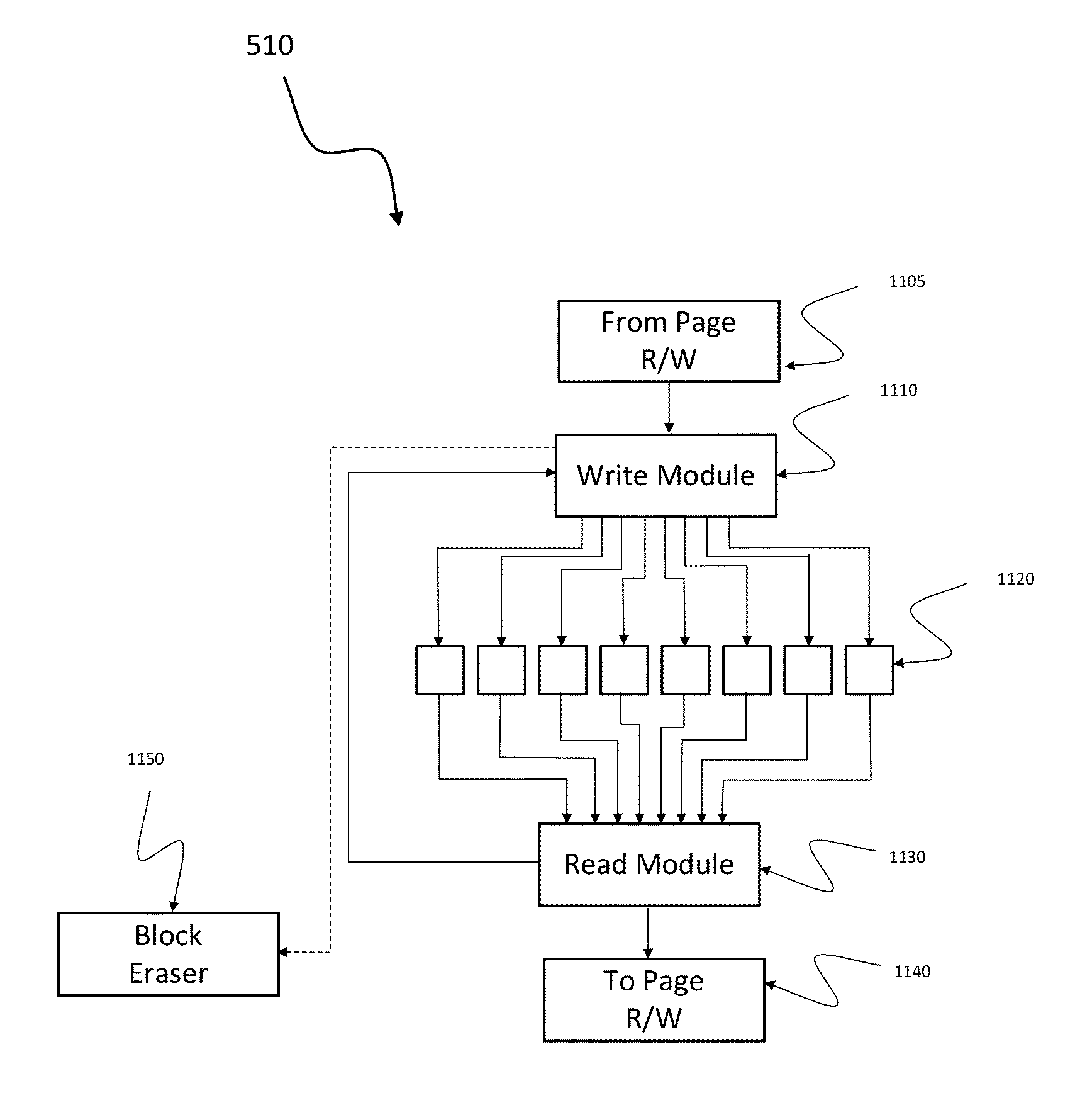
[0038]FIG. 5 illustrates a structure of a cell unit 130 that might be used in a memory storage device according to one embodiment of the present invention. Several cells 530 within a page are grouped into one unit 520 called a “fundamental group of cells.” These cells have a common R / W Module 520 that reads the charges of th...


PUM


Abstract

A method is disclosed for storing information on non-volatile memory which can rewrite memory cells multiple times before a block needs to be erased. The information to be stored is transformed into a suitable form which has better robustness properties with respect to common sources of error, such as leakage of charge, or imperfect read / write units.

Description

CROSS REFERENCES[0001]This application claims priority from and is a non-provisional of U.S. Provisional Patent Application No. 61 / 504,515, filed Jul. 5, 2011, entitled “Differential Vector Storage for Non-Volatile Memory”, the entire disclosure of which is incorporated by reference herein for all purposes.[0002]The following references are herein incorporated by reference in their entirety for all purposes:[0003]U.S. patent application Ser. No. 12 / 784,414, filed May 20, 2010, naming Harm Cronie and Amin Shokrollahi, and entitled “ORTHOGONAL DIFFERENTIAL VECTOR SIGNALING” (hereafter referred to as “Cronie I”).[0004]U.S. patent application Ser. No. 12 / 982,777, filed Dec. 30, 2010, naming Harm Cronie and Amin Shokrollahi, and entitled “POWER AND PIN EFFICIENT CHIP-TO-CHIP COMMUNICATIONS WITH COMMON-MODE REJECTION AND SSO RESILIENCE” (hereafter referred to as “Cronie II”).[0005]U.S. patent application Ser. No. 13 / 030,027, filed Feb. 17, 2011, naming Harm Cronie, Amin Shokrollahi, and A...

Claims


Application Information

Patent Timeline
IPC IPC(8): G06F12/00
CPCG06F11/1068G11C11/5642G11C11/5628
Inventor CRONIE, HARMSHOKROLLAHI, AMIN
Owner KANDOU LABS
Why Eureka
Try Eureka