
Combination directional and non-directional bone tamp

a bone tamping and directional technology, applied in the field of surgical procedures, can solve the problems of reducing the recovery period, presenting minimally invasive procedures, and requiring more time for minimally invasive procedures, so as to enhance the stability of the interface and maintain stability

Active Publication Date: 2013-01-10
KYPHON
View PDF3 Cites 26 Cited by
  • Summary
  • Abstract
  • Description
  • Claims
  • Application Information

AI Technical Summary

Benefits of technology

The patent text describes a system for expanding a cannula through a bone tunnel using a bone tamp. The bone tamp has an elongated distal tip that engages with the cannula to enhance stability during expansion. The system also includes accessory instruments such as an access cannula, introducer, guide pin, drill, curette, access needle, and material delivery nozzle for delivering bone filler material. The technical effects of this system include improved stability and efficiency during bone tunnel expansion and delivery of bone filler material.

Problems solved by technology

In contrast to an open procedure for the same purpose, a minimally invasive procedure will generally be less traumatic to the patient and result in a reduced recovery period.
However, there are numerous challenges that minimally invasive procedures present.
For example, minimally invasive procedures are typically more time-consuming than their open procedure analogues due to the challenges of working within a constrained operative pathway.
In addition, due to the specialized instruments required for such procedures, efforts to enable flexibility / adaptability in the face of varying surgical scenarios can significantly increase the number (and hence, cost) of a given minimally invasive surgical system.
However, depending on the nature of the VCF and / or the condition of the cancellous bone within the vertebral body, a directional bone tamp that expands radially in some directions but not others can improve procedure efficacy.
However, this undesirably reduces physician flexibility when performing a kyphoplasty procedure, and also increases procedure cost whenever a directional bone tamp is required.

Method used


Image

  • Combination directional and non-directional bone tamp
  • Combination directional and non-directional bone tamp
  • Combination directional and non-directional bone tamp

Examples


Embodiment Construction

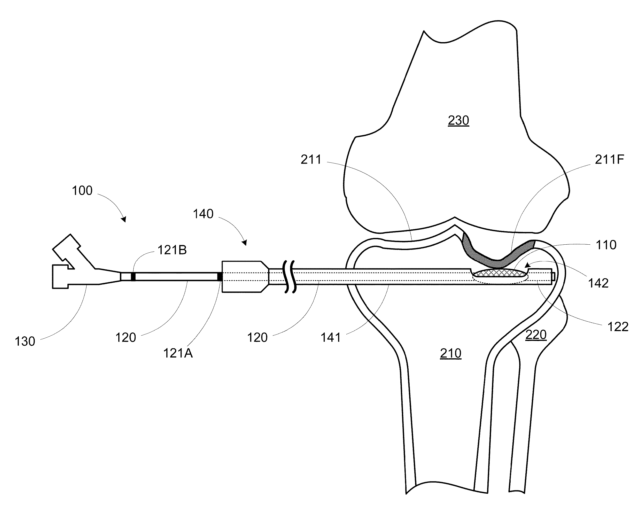
[0019]By pairing a cannula having both a side port and an open distal end with an expandable bone tamp that is extendable out the open distal end of the cannula, both non-directional and directional bone manipulation can be performed using the same bone tamp.

[0020]FIG. 1 shows a diagram of a kit 101 for use in performing a minimally invasive surgical procedure. Kit 101 includes an expandable bone tamp 100 and a cannula 140. Expandable bone tamp 100 includes an expandable structure 110 (e.g., an inflatable structure such as a balloon, or a mechanically expandable or deformable structure) mounted on the distal end of an elongate shaft 120. Expandable structure 110 is configured such that when in an unexpanded state, expandable structure 110 can be driven through an inner lumen 140L of cannula 140 by elongate shaft 120.

[0021]Cannula 140 includes a shaft 141 that defines the inner lumen 140L extending between a proximal opening 144 and a distal opening 143 of cannula 140. Shaft 141 also...


PUM


Abstract

A minimally invasive surgical system can include a cannula having a side port and an open distal end, and an expandable bone tamp. The bone tamp includes an elongate shaft coupled to an expandable element. The elongate shaft has a length adapted to align the expandable element with the side port or extend the expandable element completely beyond the distal opening of the cannula. In this manner, the cannula and bone tamp enable either directional (i.e., through the side port) or non-directional (i.e., completely outside the cannula) bone tamping.

Description

FIELD OF THE INVENTION[0001]The invention relates to a system and method for performing a surgical procedure, and in particular, to a percutaneous bone manipulation system that enables both directional and non-directional bone manipulation.BACKGROUND OF THE INVENTION[0002]A minimally invasive procedure is a medical procedure that is performed through the skin or an anatomical opening. In contrast to an open procedure for the same purpose, a minimally invasive procedure will generally be less traumatic to the patient and result in a reduced recovery period.[0003]However, there are numerous challenges that minimally invasive procedures present. For example, minimally invasive procedures are typically more time-consuming than their open procedure analogues due to the challenges of working within a constrained operative pathway. In addition, due to the specialized instruments required for such procedures, efforts to enable flexibility / adaptability in the face of varying surgical scenari...

Claims


Application Information

Patent Timeline
Patent Type & Authority Applications(United States)
IPC IPC(8): A61B17/56
CPCA61B17/8811A61B17/8855A61B17/8822
Inventor BROOME, CHARLES BRANDONGOSHAYESHGAR, MOJAN
Owner KYPHON
Learn More