Automotive fuel system

Inactive Publication Date: 2013-01-10
FUEL CONCEPTS OF AMERICA
View PDF3 Cites 0 Cited by
  • Summary
  • Abstract
  • Description
  • Claims
  • Application Information

AI Technical Summary

Benefits of technology

The present invention is about improving fuel economy in combustion engines by using an electronic fuel injector to meter fuel into the engine. This allows for calibration of fuel injected based on the engine's displacement and fuel utilization rate. The invention also includes a control circuit that can vary the frequency of the fuel injector's operation, making it difficult for tampering. The method of injecting fuel into the engine's PCV circuit and delivering it to the intake manifold leads to improved engine operation and fuel economy. The invention can be used in various types of engines and can benefit multiple industries.

Problems solved by technology

Using suitably encrypted software, this makes it difficult for persons to tamper with the system.

Method used


Image

  • Automotive fuel system
  • Automotive fuel system
  • Automotive fuel system

Examples


Embodiment Construction

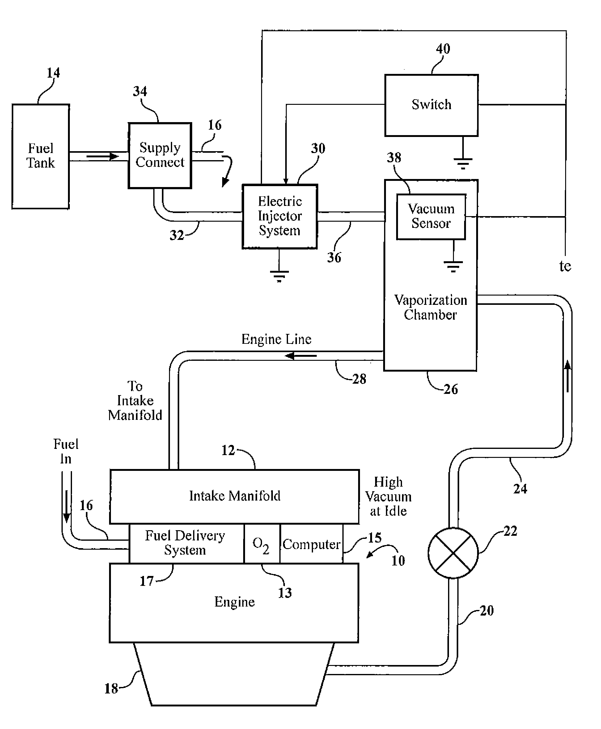
[0016]Referring now to FIG. 1, there is shown an internal combustion engine (ICE) 10 of the type having one or more pistons operating in cylinders (not shown) to produce power which can be used to propel an automotive vehicle in conventional fashion. The engine 10 is equipped with an intake manifold 12, fuel source 14 in the form of a conventional fuel tank, the tank having a fuel supply line 16 which runs to a fuel delivery system 17 such as a carburetor or fuel injection system, and thence to the engine 10. It will be understood that the intake manifold 12 is used primarily to provide air to the engine 10 and that the fuel delivery system 17, particularly if it is of the fuel injection type, may be physically separate from the intake manifold but is in operative association therewith so that the injected fuel eventually is taken up into and distributed within the air which is delivered to the combustion chambers of the pistons and cylinders within the engine 10. The engine 10 is e...


PUM


Abstract

A PCV circuit for an internal combustion engine is modified to deliver the PCV fluid to an atomization chamber which also receives fuel from an electronic fuel injector tapped into the main vehicle fuel supply. The fuel from the injector is thoroughly vaporized in and / or immediately downstream of the chamber and conveyed to the vehicle intake manifold. A switch cuts off operation of the fuel injector at high load / high throttle setting conditions. The injector operates at a constant frequency with a selected ON time.

Description

FIELD OF THE INVENTION[0001]The invention relates to fuel systems and more particularly to a fuel system for an internal combustion engine (ICE) having a PCV circuit or the like wherein the objective is to improve the fuel economy of the internal combustion engine.BACKGROUND OF THE INVENTION[0002]Positive crankcase ventilation (PCV) circuits / systems and similar vacuum intake ports are in common use in gasoline burning internal combustion engines for automobiles in the United States and elsewhere. It is well known that the purpose and function of such systems is to collect blow-by from the engine crankcase and deliver it to the intake manifold under all but high-load / high-throttle setting conditions. In and of themselves, these systems do little or nothing to improve engine efficiency or fuel economy.[0003]U.S. Pat. No. 7,117,859 discloses a system for metering fuel through a needle valve into fluid which is diverted from an automotive PCV circuit, and thoroughly vaporizing the fuel ...

Claims


Application Information

Patent Timeline
IPC IPC(8): F01M13/00
CPCF02D41/30F02D41/3094F02M25/06F02D2250/08F01M2013/0466F01M2013/0483F01M13/04
Inventor GHAFARI, C. JOSEPHMARTIN, ROY
Owner FUEL CONCEPTS OF AMERICA
Why Eureka
Try Eureka