Diaphragm-type carburetors

a diaphragm type, carburetor technology, applied in the direction of liquid fuel feeders, machines/engines, separation processes, etc., can solve the problems of reducing engine speed and engine stoppage, unstable fuel pressure within the metering chamber, excessive lean air-fuel mixture, etc., to prevent the air-fuel mixture from becoming excessively lean, stable supply of fuel, and prevent the effect of unstable fuel pressur

Active Publication Date: 2007-01-18
ZAMA JAPAN
View PDF13 Cites 6 Cited by
  • Summary
  • Abstract
  • Description
  • Claims
  • Application Information

AI Technical Summary

Benefits of technology

[0014] Thus, it is an advantage of the present invention that it is possible to prevent the air-fuel mixture from becoming excessively lean and to prevent the fuel pressure from becoming unstable. Therefore, the carburetor may stably supply the fuel to the engine and improve engine operation.
[0015] Further objects, features, and advantages of the present invention will be understood from the following detailed description of preferred embodiments of the present invention with reference to the accompanying figures.

Problems solved by technology

In particular, a fuel vapor bubble may be generated due to elevated environmental temperatures during summer time so as to create a problem.
If the bubble of the generated fuel vapor is introduced to the metering chamber, and is delivered to an intake passage from a main nozzle or the like, a reduction of engine speed and an engine stoppage may occur due to a lean air-fuel mixture.
Further, the technique described in Japanese Unexamined Patent Publication No. 2000-297702 and the technique described in Japanese Unexamined Patent Publication No. 2003-166444 may not completely eliminate the problem that the fuel vapor is discharged to the intake passage from the upper portion of the metering chamber so as to make the air-fuel mixture excessively lean, and create a risk that the fuel pressure within the metering chamber becomes unstable.

Method used


Image

  • Diaphragm-type carburetors
  • Diaphragm-type carburetors
  • Diaphragm-type carburetors

Examples


Embodiment Construction

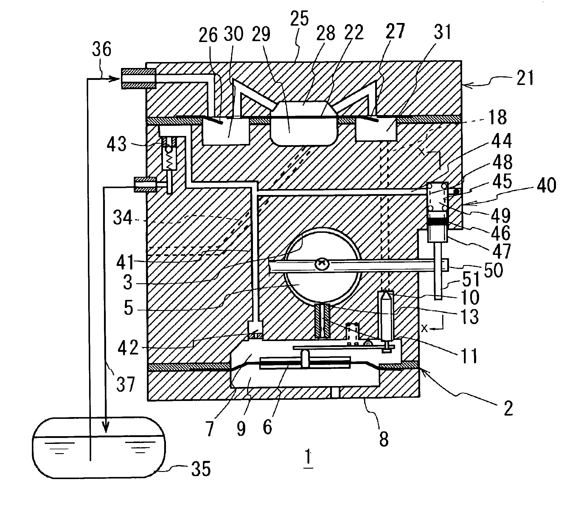
[0020] A description will be given of a preferred embodiment the present invention with reference to the accompanying drawings. As shown by a cross-sectional view in FIG. 1, a main body 2 of a diaphragm-type carburetor 1 has a transverse intake passage 3 provided with a throttle valve 5, and a metering chamber 7 may be disposed in a lower surface of the main body 2. The metering chamber 7 is separated from an atmospheric air chamber 9 within a diaphragm cover 8 by a diaphragm 6. Fuel is fed into metering chamber 7 from a fuel pump 21 through an inlet valve 10 opened and closed in correspondence to a displacement of diaphragm 6, and the fuel is discharged to intake passage 3 from a main nozzle 13 through a main fuel passage 11.

[0021] A pump diaphragm 22 and a pump cover 25 are arranged in stacks in the main body 2, and an inlet check valve 26 and an outlet check valve 27 are formed in pump diaphragm 22. Further, a pulse chamber 29 is disposed in main body 2 side with respect to pump...


PUM

PropertyMeasurementUnit
pressureaaaaaaaaaa
constant pressureaaaaaaaaaa
timeaaaaaaaaaa

Abstract

The carburetor prevents an air-fuel mixture from becoming excessively lean and prevents a fuel pressure from becoming unstable, thereby making it possible to stably supply a fuel to an engine, in a diaphragm-type carburetor with a pressure regulating means. A diaphragm-type carburetor includes a fuel pump using a pulsation pressure generated in a crank chamber of an engine or an intake pipe as a driving force, and a metering chamber having a diaphragm and a lever mechanism and provided with fuel at a desired constant pressure. The diaphragm-type carburetor includes a bubble discharge path connecting the metering chamber to other predetermined discharge portions and with a check valve in each of an inlet side and an outlet side. A bubble removing pump is connected to the bubble discharge path, withdraws the bubble to the bubble discharge path from the metering chamber in conjunction with a closing or opening operation of a throttle shaft by a driver or operator and discharging the withdrawn bubble to the discharge portion in conjunction with an opening or closing operation of the throttle shaft.

Description

BACKGROUND OF THE INVENTION [0001] 1. Field of the Invention [0002] The present invention relates to diaphragm-type carburetors preferably for use in general purpose engines and provided with a metering chamber maintaining a desired fuel pressure by a diaphragm and a lever mechanism, and, more particularly, to diaphragm-type carburetors provided with a means for removing a bubble of a fuel vapor introduced to the metering chamber or generated within the metering chamber. [0003] 2. Description of Related Art [0004] A diaphragm-type carburetor frequently is used for supplying a fuel to a general purpose engine, particularly, a general purpose engine having a small displacement, and an inner portion of such diaphragm-type carburetors generally is provided with a metering chamber (e.g., a constant pressure chamber) for obtaining a constant fuel pressure which provides a reference for fuel metering by a metering diaphragm and a metering lever mechanism. [0005] Such a metering chamber may...

Claims


Application Information

Patent Timeline
Patent Type & Authority Applications(United States)
IPC IPC(8): F02M17/04
CPCF02M17/04Y10S261/81Y10S261/19
Inventor ARAKI, SATORU
Owner ZAMA JAPAN
Why Eureka
Try Eureka