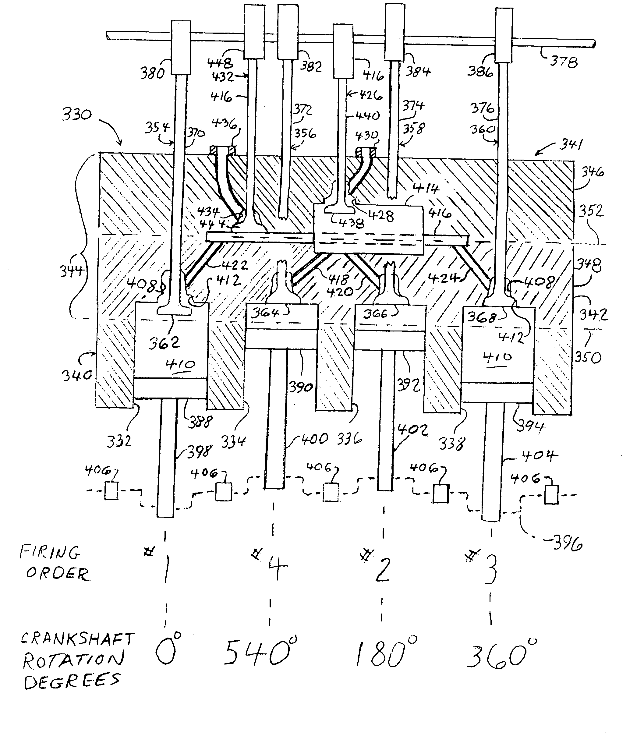
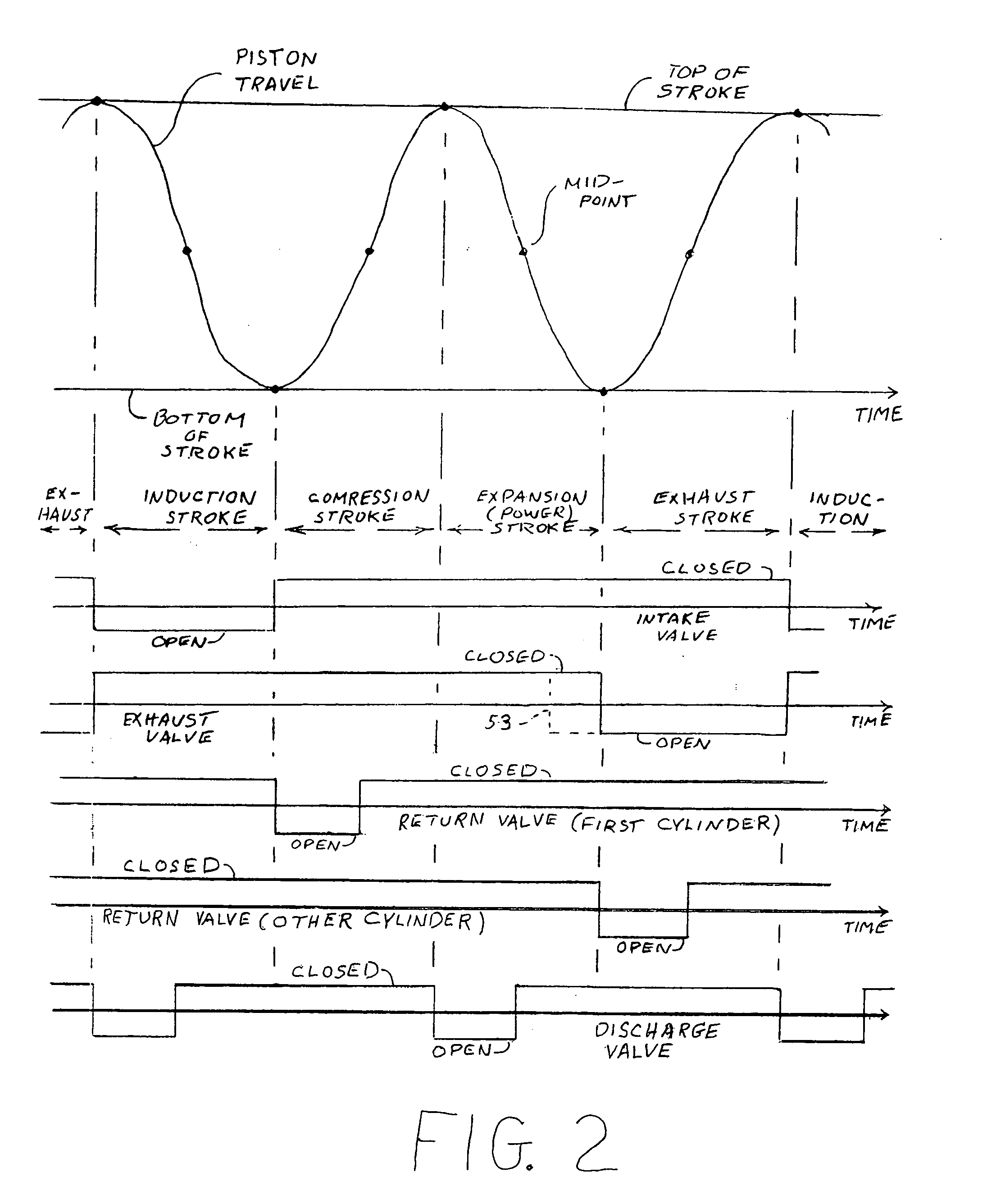
[0012] The operation of the return valves is synchronized with the operation of the intake valves. Such synchronization can be accomplished by driving the return valve of an individual one of the cylinders by an additional
cam on a
camshaft which operates either one or both of the intake and exhaust valves of the cylinder, or by use of a further
camshaft. The return valve is open during a portion of the compression stroke of its cylinder. During an open state of the return valve, the corresponding
discharge valve is closed, and the
interior space of the cylinder connects via the return port to the
interior space of the corresponding holding tank. This effectively enlarges the interior size of the cylinder during the portion of the compression stroke when the return valve is open. The volume of the holding tank is essentially equal to the volume of the cylinder at the point in time wherein the
piston has moved approximately half way along the compression stroke. Therefore, at this point in time, half of the charge of the cylinder, namely the air-fuel mix (of the
gasoline engine) or the air (of the
diesel engine) is located in the cylinder and the other half of the charge is located in the holding tank.
[0013] Thereupon, the return valve is closed, and the compression stroke continues with only half of the charge being present in the cylinder. The withdrawn charge is held within the holding tank until a later moment when it can be discharged into the return manifold. The discharging is accomplished by an opening of the
discharge valve. In the practice of the invention, the discharging of the returned charges (gases) of the various holding tanks is accomplished in a manner which encourages a relatively smooth flow of the returned charges from the return manifold into the inlet to the
carburetor or the fuel-injection
assembly. The smooth flow of the returned air or air-fuel mix ensures that subsequent metering of the air or air-fuel mix can be accomplished in a normal manner without disruption by the process of extracting air or air-fuel mix from the cylinders.
[0016] The
cylinder head is constructed of an upper section and a lower section, wherein the upper section and the lower section may be coupled together via a
gasket to facilitate manufacture, and wherein the lower section is disposed between the upper section and the
cylinder block. One or more holding tanks, depending on the number of the cylinders, are located at an interface between the two sections. Thereby, during
assembly of the
cylinder head, prior to a joining of the two sections via the
gasket, access is available to the interior of a holding tank for
insertion of the discharge valve into the upper section of the housing. This facilitates construction.
[0018] In accordance with an important feature of the invention, the overall physical size of the engine is reduced by reducing the overall volume of the totality of holding tanks disposed within a single
cylinder head, as in the case of a straight four-
cylinder engine, or disposed within a plurality of cylinder heads, as in the case of a V8 configuration of engine. The reduction in the overall volume of the totality of the holding tanks is accomplished by sharing a single one of the holding tanks with a plurality of engine cylinders. The height of the engine can be reduced by building the holding tank(s) in a pancake shape wherein a tank extends transversely of the
cylinder block with a relatively small dimension in terms of the height of the tank(s). It is recognized that, as a practical matter, a holding tank may have an
irregular shape to conform to the
layout of other components (such as valve stems, oil passages, and
coolant passages, by way of example) in a particular construction of engine.
[0021] In such an engine, with respect to the operation of each of the two cylinder groups, the compression stroke of the first
piston occurs concurrently with the exhaust stroke of the second piston. This embodiment of the invention enables the two cylinders to share a single holding tank located within their common cylinder head because the return valve associated with the first of the two pistons is open (during a portion of the compression stroke) when the return valve associated with the second of the two pistons is closed (during the exhaust stroke). The discharge valve, located at an exit of the common holding tank, has the opportunity to open during a portion of the intake stroke of either one of the two cylinders, this corresponding to the time of occurrence of the expansion (power) stroke in the other of the two cylinders. In this way, the operation of the first cylinder with its first piston and the common holding tank can take place without interference from the operation of the second cylinder with its second piston and the common holding tank.
[0022] Furthermore, in the foregoing engine, with respect to the outputting of gas from each of the holding tanks to the return manifold, it is noted that the movements of the pistons in the second of the cylinder groups is delayed from the piston movement of the first cylinder group by one quarter of the four-stroke cycle. As a result, the operations of the two discharge valves associated respectively with the two holding tanks are staggered, such the one discharge valve is open only during a period of time when the other discharge valve is closed. This provides for a uniform pattern in the flow gasses from the two holding tanks into the return manifold for enhanced operation of the engine.

