
System and method for renewable electrical power production using wave energy

a renewable electrical power and wave energy technology, applied in the direction of mechanical equipment, machines/engines, transportation and packaging, etc., can solve the problems of reducing the efficiency of the apparatus, the apparatus cannot be used in great depths of water, and the engineering problem is complex and difficult, so as to achieve the effect of efficiently extracting energy

Inactive Publication Date: 2013-01-10
WAVE ENERGY CONVERSION CORP OF AMERICA
View PDF25 Cites 36 Cited by
  • Summary
  • Abstract
  • Description
  • Claims
  • Application Information

AI Technical Summary

Benefits of technology

The present invention aims to create a system and method that can efficiently extract energy from a wide range of wavelengths of ocean waves. This is done by using a buoyant apparatus that can be moored using conventional or novel techniques. The technical effect is that the system and method can overcome the inefficiencies of previous components in the market.

Problems solved by technology

The fixed structure is usually mounted on the sea bed and this produces vast engineering problems and difficulties.
It also means that such apparatus cannot be used in great depths of water.
This greatly reduces the efficiency of the apparatus.
All of the engines disclosed in these patents are mechanically complex and highly inefficient.
Few devices utilize both forms of energy.
Additionally, many early wave motors are extremely complex mechanically.
As a result, such wave motors had to be very rugged and heavy to withstand the wide spectrum of wave energy incident upon them.
The inefficiency, capital cost and complexity of such prior art wave motors caused them to be unsuccessful.
Unfortunately, such a linearly coupled collector cannot efficiently trap wave energy.
Because waves differ in amplitude by as much as two orders of magnitude, any device that extracts power by linearly coupling wave movement to gears or pistons will have to be inefficient in extracting power from either the high or low amplitude end of the wave power spectrum.
Theoretically, a single float acting alone, even if it is the proper size, can only absorb a fraction of the available power from a wave incident upon it.
This fact, as well as the fact that wave motors taught by the prior art do not couple efficiently into either the frequency or amplitude spectrum of ocean waves, have caused all prior art wave motors to be very inefficient.
These early patents relied on mechanical linkages between fixed floats to trap the rocking, lifting, falling, or longitudinal motion of the waves but were highly inefficient due to their mechanical complexities.
The Hagen-array system of hinged rafts suffers from the fact that the unit length of the rafts perpendicular to the crests (parallel to the line of incidence) must be approximately one wave length of the incident waves.
The result is good efficiency relative to the beam dimension of the rafts but poor efficiency in terms of energy extracted per raft size or weight.
The poor efficiency results because the Hagen-array system does not make use of the physical parameters of the rafts other than unit length to tune the system properly so as to respond to the broad spectrum of wave frequencies that occur in the ocean.
The device described in this patent is an efficient absorber but suffers from the lack of stable reference necessary for power extraction.
Although the device incorporates several features that improve the efficiency of energy capture, the concept fails to incorporate the more important features necessary for economical wave energy generation efficiency.
The supporting structure or mooring system required to operate many of these inventions, however, is quite elaborate and costly.
No prior art found by the inventor teaches the advantages of tying together a group of floats in an array to form a wave trap to capture reflected and transmitted wave energy.
Also, no prior art found by the inventor teaches the nonlinear coupling of the floats to their associated power extraction devices.
The prior art is limited either to the mechanism by which power is transferred from wave to floating structure or to methods of converting the motion of a floating structure to useful power.
Further, the prior art does not match the power train impedance to the incident wave characteristics so as to optimize power absorption and short time energy storage to achieve maximum power train efficiency.
The prior art does not analyze the economic factors that must be considered for an energy system to provide base load power to a shore installation.

Method used


Image

  • System and method for renewable electrical power production using wave energy
  • System and method for renewable electrical power production using wave energy
  • System and method for renewable electrical power production using wave energy

Examples


first preferred embodiment

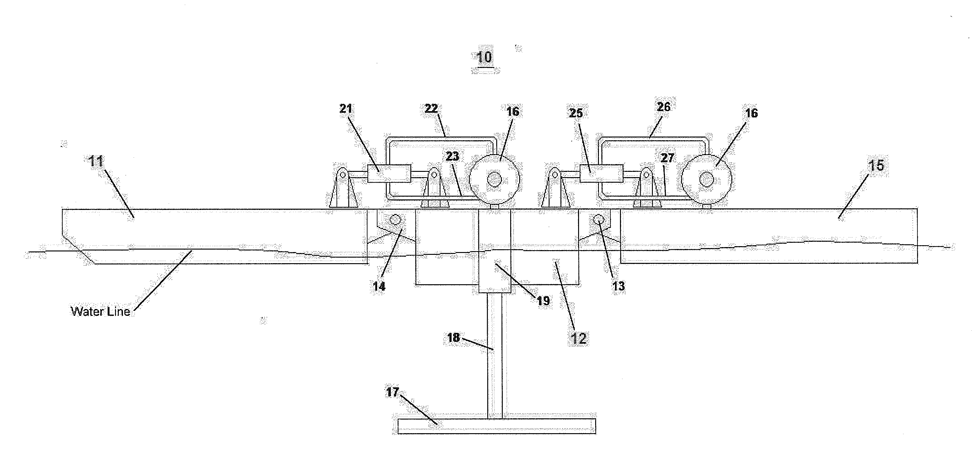
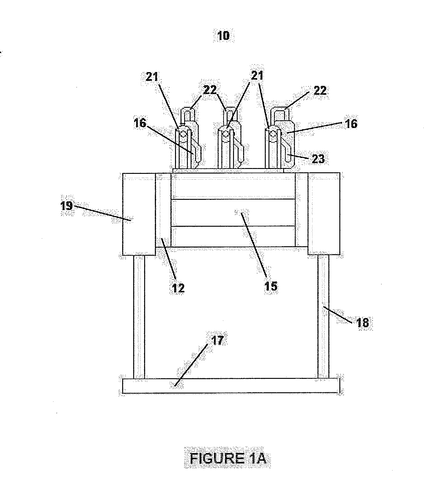
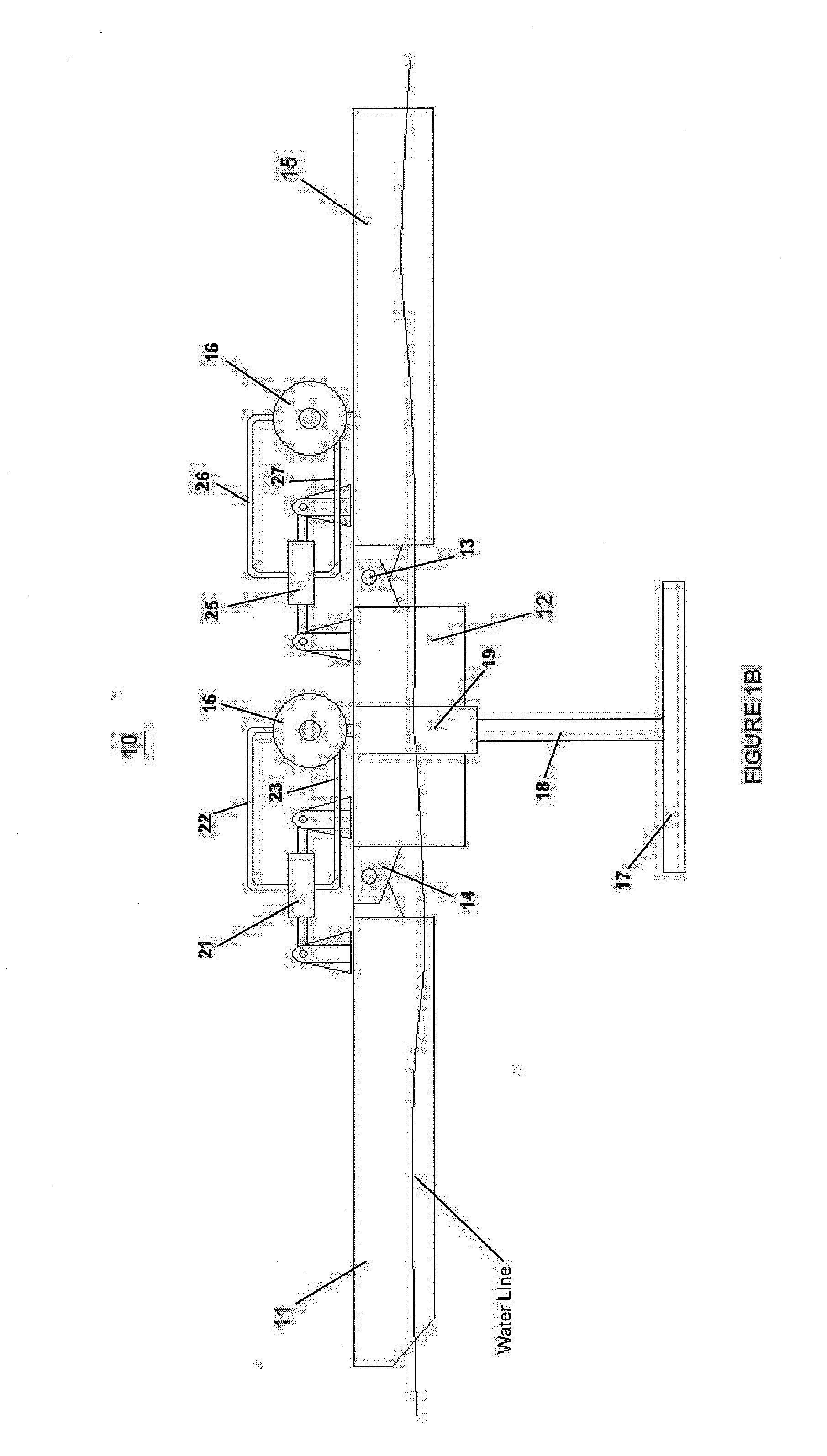
[0065]In a first preferred embodiment of the invention for a system that produces electricity through the conversion of wave energy, as shown in FIGS. 1A-1C as an example, one or a plurality of barges will pitch at the frequency of the incident waves; radiated waves will then be created which result in a destructive interference of the radial and incident waves, causing focusing on the system by diffraction. Diffraction is the movement of energy in a direction perpendicular to the direction of wave travel. For example, if a wave is blocked by an obstruction, diffraction allows wave energy to fill in the “shadow” behind that obstruction.

[0066]Absorption of wave energy by a floating body (i.e., a barge) is directly related to that floating body's ability to generate a wave that cancels the incident wave. The system of the invention is intended to generate waves radiating to the front as well as the sides. This ability allows it to capture wave energy from the sides as well.

[0067]Exper...

second preferred embodiment

[0093]During periods of highly active surface waves, which can be destructive, the system may be configured to be submerged so as to prevent damage to any of the system components or sub-systems, while still interacting with the wave motion or currents below the surface of the water. As is known in the art, ocean wave-energy conversion devices are naturally sited at locations that have high-energy waves. These devices are tuned to generate the most power in the wave frequencies that have the highest power, on average. However, extreme storms can create conditions that can damage the wave-energy conversion devices. Most recently, the Oceanlinx full-scale prototype off the east coast of Australia was ripped from its moorings and destroyed by storm waves in May 2010.

[0094]A novel strategy for severe weather survival of an ocean wave-energy conversion system according to the present invention embodies submerging the system when wave heights become excessive. Beneath the surface, the mot...


PUM


Abstract

Wave energy conversion to produce electricity uses wave-engaging articulated, forward and after barges connected to a center inertial barge. A damper plate attached to the central barge minimizes heaving to increase stability. The barges use composite materials, steel or other materials that can withstand the impact and wear caused by a corrosive weather environment. A movable ballast weight in each barge adjusts the mass moment of inertia, and changes the natural pitching frequency. Electrical energy is generated from the motions of the barges and the movement of the movable ballast weights being converted by linear induction motor / generators and / or Pelton Wheel hydraulic systems connected to electrical generators. A dynamic computer control system controls the energy generating system to keep the forward / after barges and the movable ballast moving in phase with the wave excitation force. During dangerous wave action, the system is submerged and then re-surfaced when the waves have subsided.

Description

[0001]This application is a continuation-in-part of PCT Application No. U.S.2011 / 001121 filed Jun. 23, 2011, which claims priority to U.S. Provisional Application No. 61 / 398,203 filed on Jun. 23, 2010, both of which this application claims priority thereto. Both prior applications are hereby incorporated by reference.BACKGROUND OF THE INVENTION[0002]1. Field of the Invention[0003]The present invention relates to a system and method for converting into useful energy movements imparted thereto by the movement of water, preferably sea waves and / or sea currents.[0004]The present invention also relates to a power generation system which extracts useful power from water waves. In particular, the invention relates to the interaction of various elements of the design of a wave driven generator unit. More specifically, the present invention absorbs wave energy, converts that energy into electrical energy, and transports that electrical energy from its offshore point of generation to a land-b...

Claims


Application Information

Patent Timeline
IPC IPC(8): F03B13/14F03G6/00
CPCF03B13/20Y02E10/38Y02E10/46F05B2240/97F05B2270/202Y02E10/20Y02E10/30F03B13/10F03B13/14
Inventor CUNNINGHAM, BRIAN T.MORLEY, DANIEL C.
Owner WAVE ENERGY CONVERSION CORP OF AMERICA
Learn More