projector
a projector and projection technology, applied in the field of projectors, can solve the problems of deterioration of image quality of projected images, and direct falling of pins, and achieve the effect of reducing the number of units taken from the base member, and reducing the number of pins
- Summary
- Abstract
- Description
- Claims
- Application Information
AI Technical Summary
Benefits of technology
Problems solved by technology
Method used
Image
Examples
first embodiment
[0032]Hereinafter, a projector according to a first embodiment will be described with reference to the drawings.
[0033]The projector of this embodiment modulates a luminous flux emitted from a light source according to image information and projects the luminous flux onto a screen or the like in an enlarged manner.
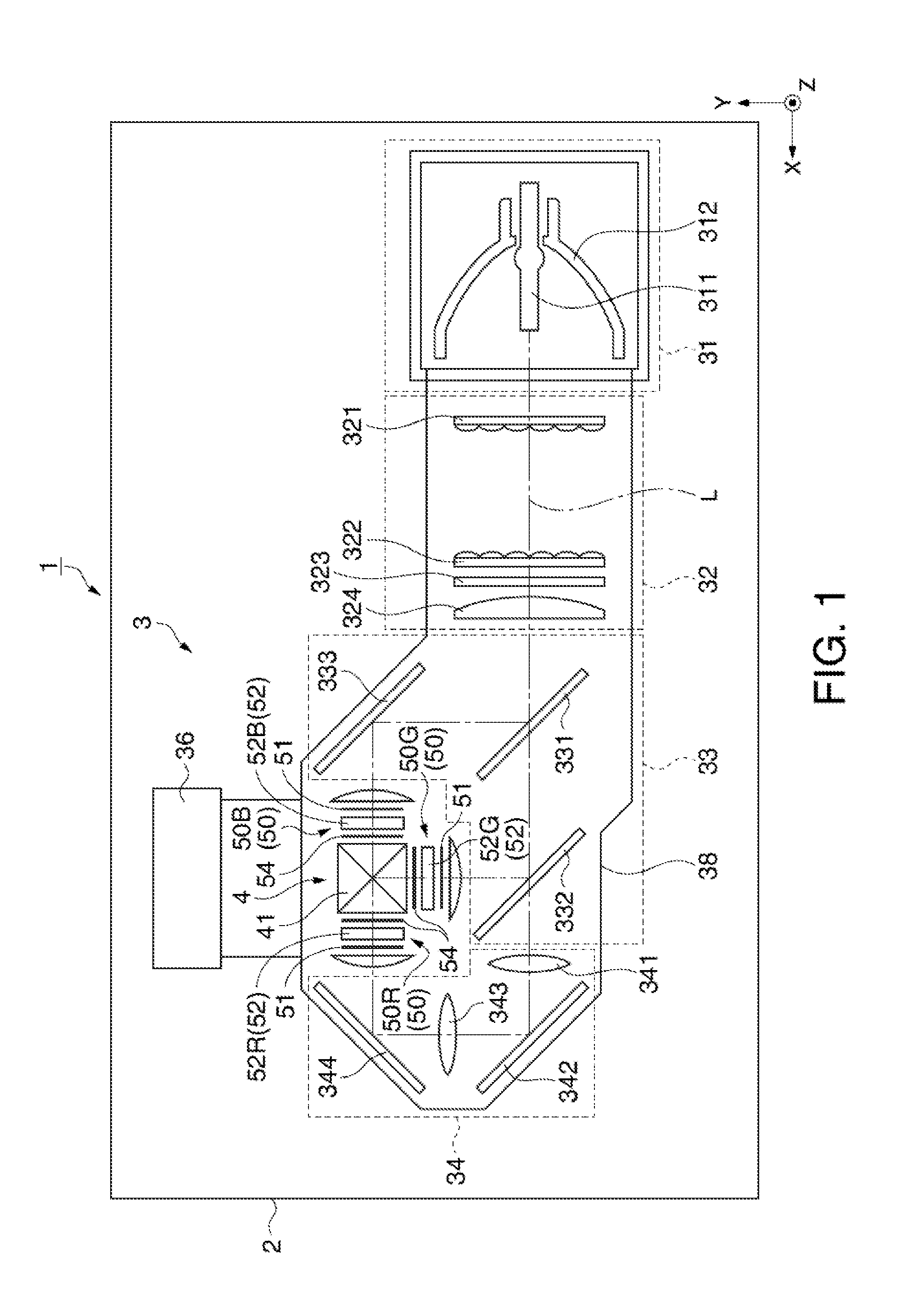
[0034]FIG. 1 is a schematic view showing a general configuration of a projector 1 according to this embodiment.
[0035]As shown in FIG. 1, the projector 1 has an exterior casing 2 forming an exterior, a control unit (not shown), and an optical unit 3 having a light source device 31. Although not shown, a power supply unit which supplies power to the light source device 31 and the control unit, a cooling device which cools the optical unit 3, and the like are arranged inside the exterior casing 2.
[0036]The exterior casing 2 has an upper case forming an upper part and a lower case forming a lower part, though not described in detail. The exterior casing 2 is provided with a suc...
second embodiment
[0099]Next, a projector 1 according to a second embodiment will be described with reference to the drawings. Hereinafter, similar structures and similar members to the projector 1 of the first embodiment are denoted by the same reference numerals and detailed descriptions thereof are omitted or simplified.
[0100]The projector 1 of this embodiment has a supporting member 27 of a different shape from the supporting member 7 of the first embodiment.
[0101]FIG. 6 is a plan view schematically showing the supporting member 27 of this embodiment.
[0102]The supporting member 27 is worked out of a metallic plate member and has a body portion 271, and first plate-like portions 272a, 272b and second plate-like portions 273a, 273b which are protruding from the four corners of the body portion 271, as shown in FIG. 6.
[0103]The first plate-like portions 272a, 272b are formed protruding from the bottom left and right corners of the body portion 271, as viewed in FIG. 6, and each having an inclination...
modification 1
[0110]The first plate-like portions 73a, 73b, 73c, 73d of the first embodiment are protruding and inclined from the vertical plane Sv in such a way that the plate surfaces 73S face the optical axis 52L. However, the first plate-like portions may be inclined from the vertical plane Sv by protruding in other directions.
[0111]FIG. 7 is a plan view schematically showing a supporting member 17 according to Modification 1.
[0112]The supporting member 17 has first plate-like portions 173a, 173b, 173c, 173d protruding from the four corners of a body portion 171. The first plate-like portions 173a, 173b, 173c, 173d are formed protruding in such away that plate surfaces 173S face out-of-plane directions of the body portion 171, and having an inclination angle θ1 from the vertical plane Sv.
[0113]The first plate-like portions 173a, 173b, 173c, 173d are formed in such a way that the first plate-like portions 173a, 173c situated on one diagonal line are along a first direction 8A while the first p...
PUM
| Property | Measurement | Unit |
|---|---|---|
| inclination angle | aaaaa | aaaaa |
| inclination angle | aaaaa | aaaaa |
| inclination angle | aaaaa | aaaaa |
Abstract
Description
Claims
Application Information
 - R&D
- Intellectual Property
- Life Sciences
- Materials
- Tech Scout
- Unparalleled Data Quality
- Higher Quality Content
- 60% Fewer Hallucinations
Browse by: Latest US Patents, China's latest patents, Technical Efficacy Thesaurus, Application Domain, Technology Topic, Popular Technical Reports.
© 2025 PatSnap. All rights reserved.Legal|Privacy policy|Modern Slavery Act Transparency Statement|Sitemap|About US| Contact US: help@patsnap.com


