
Prepreg, fiber-reinforced composite material, and method for producing prepreg

Active Publication Date: 2012-12-27
TORAY IND INC
View PDF5 Cites 21 Cited by
  • Summary
  • Abstract
  • Description
  • Claims
  • Application Information

AI Technical Summary

Benefits of technology

[0031]According to the present invention, it is possible to provide a fiber reinforced composite material which excels in rigidity, strength, and vibration damping properties; and a prepreg which is suitably used for production thereof. That is, by means of the fiber reinforced composite material and the prepreg of the present invention, it is possible to improve vibration damping properties of fiber reinforced composite material without reducing rigidity or strength, by causing urethane particles having high vibration damping properties and a three-dimensional cross-linked structure to be localized between fiber reinforced composite material layers. The present invention is useful for purposes such as improvement in the ball hitting feeling of golf club shafts, increase in shock absorbing properties of tennis rackets, and improvement in fish bite sensitivity of fishing rods.BRIEF EXPLANATION OF DRAWINGS
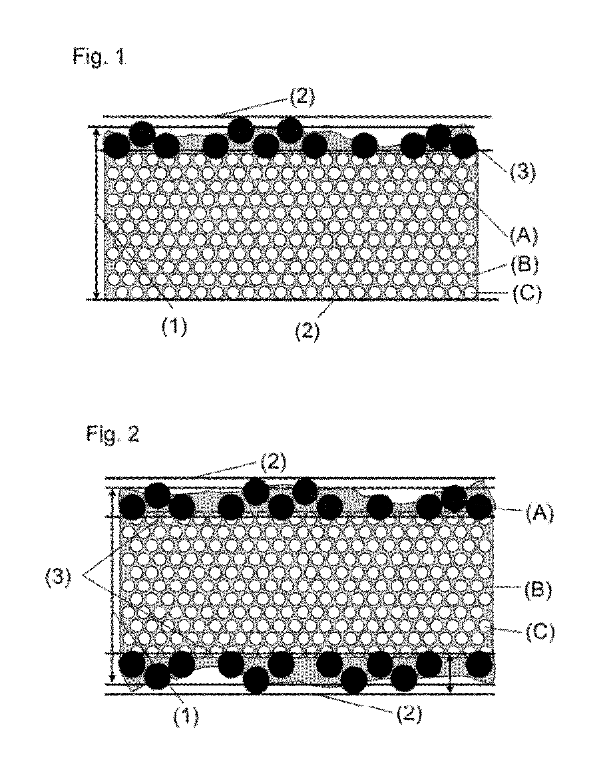
[0033]This is a cross-sectional view of a prepreg which comprises components (A) to (C) and in which component (A) is placed on one surface of a layer formed of components (B) and (C).
[0035]This is a cross-sectional view of a prepreg which comprises components (A) to (C) and in which components (A) are placed on both surfaces of a layer formed of components (B) and (C).
[0037]This is a cross-sectional view of a prepreg which comprises components (A) to (D) and in which component (A) in a state of being contained in component (D) is placed on one surface of a layer formed of components (B) and (C).
[0039]This is a cross-sectional view of a prepreg which comprises components (A) to (D) and in which component (A) in a state of being contained in components (D) is placed on both surfaces of a layer formed of components (B) and (C).
[0041]This is a cross-sectional view of a fiber reinforced composite material which comprises components (E) to (G) and in which component (E) is placed between layers of a laminate formed of components (F) and (G).

Problems solved by technology

The cause increased vibrations transmitted to hands and an increased sense of rigidness during ball hitting.
It is known that if these vibrations are repeatedly received, fatigue accumulates in the elbow, thus causing a so-called tennis elbow, in which pain develops in the elbow.
Consequently, subsequent to lamination, a large quantity of rubber component can exist between prepreg layers.
However, since rubber particles having lower modulus than an epoxy resin enter the interior of reinforcing fiber bundles, the matrix resin's modulus decreases, resulting in a decrease in the racket rigidity and strength.
Although shock resistance and fatigue properties improve, vibration damping properties near room temperature are not sufficient.
This elastomer sheet greatly improves vibration damping properties, but significantly reduces the rigidity and the strength of the fiber reinforced material.

Method used


Image

  • Prepreg, fiber-reinforced composite material, and method for producing prepreg
  • Prepreg, fiber-reinforced composite material, and method for producing prepreg
  • Prepreg, fiber-reinforced composite material, and method for producing prepreg

Examples


examples

[0144]The present invention will now be illustrated in greater detail with reference to Examples, but it should be understood that the invention is not construed as being limited thereto.

[0145]Components (A) to (E) used in Examples and Comparative examples are as follows.

[0146](A-1): Three-dimensional cross-linked urethane particles coated with hydrophobic silica (“DAIMICBEAZ [registered trademark]” UCN-5150D manufactured by Dainichiseika Color & Chemicals Mfg. Co., Ltd.: average particle diameter 15 μm; tan δ at 10° C., 0.20; glass transition temperature −27° C.; spherical)

[0147](A-2): Three-dimensional cross-linked urethane particles coated with hydrophobic silica (“DAIMICBEAZ [registered trademark]” UCN-5070D manufactured by Dainichiseika Color & Chemicals Mfg. Co., Ltd.: average particle diameter 7 μm; tan δ at 10° C., 0.20; glass transition temperature −27° C.; spherical)

[0148](A-3): Three-dimensional cross-linked urethane particles (“Art Pearl [registered trademark]” JB-400T m...

reference examples 1 to 9 and 17 to 24

[0203]Epoxy resins shown for Reference Examples 1 to 9 and 17 to 24 in Tables 1 and 2 were heated, melt-kneaded, and then cooled to 60° C., followed by adding a curing agent and curing catalyst to prepare epoxy resin compositions. Each of these resin compositions was defoamed in a vacuum and injected in a mold which was set up so that the thickness would be 2 mm by means of a 2 mm thick Teflon (registered trademark) spacer, followed by curing under the conditions described in each Reference example to prepare a 2 mm thick cured resin. The glass transition temperatures of such cured resins are shown in Table 1 and Table 2. In Reference Examples 1 to 9 and 18 to 24, the glass transition temperature was in a sufficiently high range of not less than 100° C., but it was less than 100° C. in Reference Example 17. Furthermore, DSC analysis showed no exothermic peak for all cured resins prepared in Reference Examples, indicating that the cured resins were in a completely cured state.

reference example 10

[0204]Epoxy resins shown for Reference Examples 10 in Table 1 was melt-kneaded and then cooled to 80° C., followed by adding a curing agent to prepare an epoxy resin composition. A cured resin was produced from this resin composition by the same procedure as in Reference Example 1 except that the curing was performed at 180° C. for 2 hours. The cured resin was acceptable in terms of both glass transition temperature and exothermic peak.


PUM

PropertyMeasurementUnit
Temperatureaaaaaaaaaa
Fractionaaaaaaaaaa
Fractionaaaaaaaaaa

Abstract

A prepreg containing components (A) to (C) defined below, wherein component (A) is placed on one surface or both surfaces of a layer comprising components (B) and (C), 90% or more by area of component (A) being present in a region(s) extending from the surface(s) of the resulting prepreg containing components (A) to (C) to a depth equal to 20% of the average thickness of the prepreg: (A) urethane particles having tan δ of 0.15 or more at 10° C. and having a three-dimensional cross-linked structure, (B) a first epoxy resin composition, and (C) reinforcing fiber. The present invention provides a fiber-reinforced composite material which excels in rigidity, strength, and vibration damping properties, and a prepreg which is suitably used for production thereof, and also provides methods for production thereof.

Description

TECHNICAL FIELD[0001]The present invention relates to a fiber-reinforced composite material which excels in rigidity, strength, and vibration damping properties, and which are suitable for sports applications and general industrial applications, also relates to a prepreg which is suitably used for production thereof and a method for production thereof.[0002]More specifically, the present invention relates to a fiber-reinforced composite material which can be suitably applied to production of, for example, various frames, pipes, shafts, wheels, and curved circular plates thereof that are used in aircraft, ships, automobiles, bicycles, etc., and industrial machines such as pumps and bush cutters; tubular bodies such as golf club shafts, fishing rods, ski poles, badminton racket shafts, and tent poles; various sporting / leisure goods such as skis, snow boards, golf club heads, bicycle rims; and civil engineering and construction materials, as well as repair and reinforcement materials t...

Claims


Application Information

Patent Timeline
IPC IPC(8): B32B7/02B32B38/08B32B37/18
CPCC08G59/4021Y10T156/10C08G59/5033C08J5/24C08J2363/00C08L63/00B32B5/26B32B5/28B32B2250/05B32B2250/20B32B2260/023B32B2260/046B32B2262/106B32B2264/0292B32B2307/54B32B2307/56B32B2307/718C08J2475/04C08K7/02Y10T428/2495C08G59/4215C08J5/243C08J5/249C08L75/04C08K7/06C08J2363/02C08K2201/009
Inventor FUJIWARA, TAKAYUKIMISUMI, JUNMATSUDA, AYUMIYOSHIOKA, KENICHI
Owner TORAY IND INC
Learn More