Eureka AIR delivers breakthrough ideas for toughest innovation challenges, trusted by R&D personnel around the world.

Battery end cap

a battery and end cap technology, applied in the field of batteries, can solve the problems of affecting the purpose or utility of such a device, the danger of children's battery consumption, and the utility of these small form factor batteries, so as to increase the size of small form factor batteries without the risk of harm

Inactive Publication Date: 2012-12-20
IBM CORP
View PDF4 Cites 18 Cited by
  • Summary
  • Abstract
  • Description
  • Claims
  • Application Information

AI Technical Summary

Benefits of technology

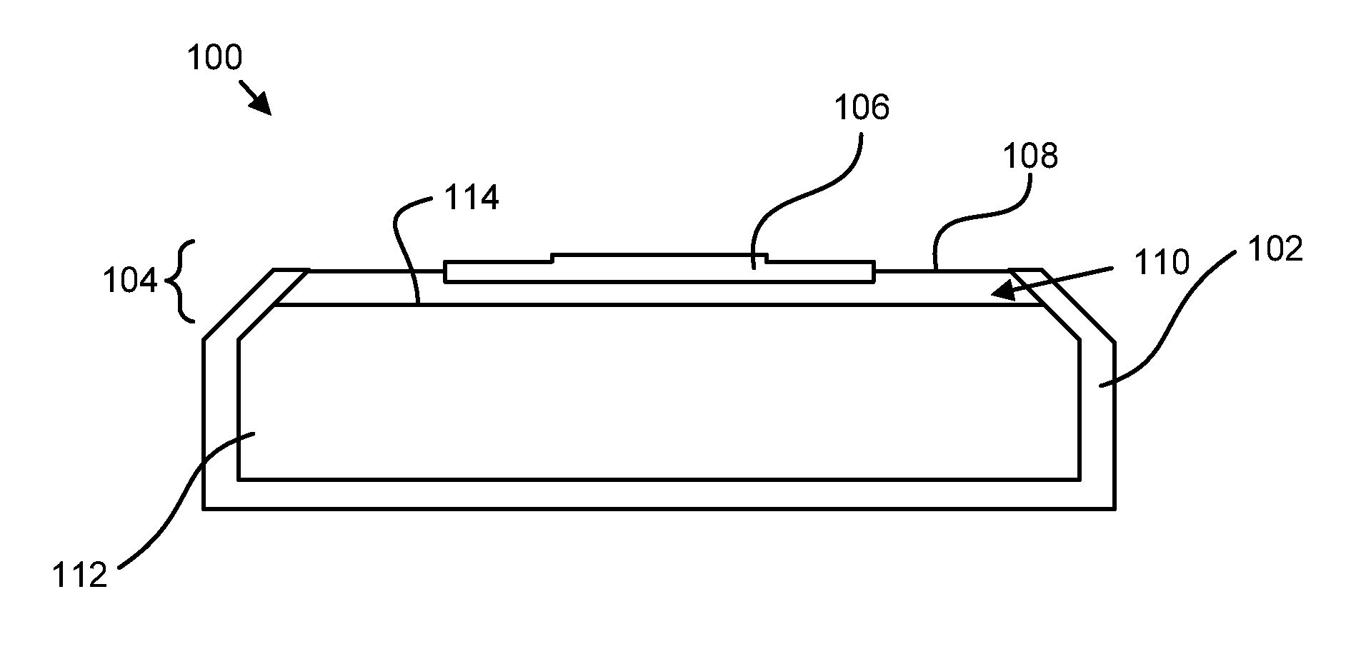
The present invention provides an apparatus, system, and method for a battery end cap that overcomes the risks of harm in case of swallowing by an adult or child. The battery end cap includes a cap terminal and a pressure sensitive switch. When the battery end cap is installed on a battery, the pressure sensitive switch is configured to bias the internal conductive surface of the cap terminal from being in electrical communication with an electrical source of the battery. The pressure sensitive switch is in a closed position when a sufficient external pressure is applied to the battery end cap and is in an open position without the sufficient external pressure. This feature helps to protect children from current flow that may be induced if ingested. The technical effects of this invention include providing safety features for small form factor batteries and ensuring that they are only slightly increased in size.

Problems solved by technology

For example, batteries having one of these small form factors are often used in such devices as watches, calculators, or even musical gift cards where a larger battery may defeat the purpose or utility of such a device.
However, the utility of these small form factor batteries is somewhat over-shadowed by their danger to children.
Because of their small form factor, these batteries are often swallowed by children.
At times, the batteries can be lodged in a child's throat, which may result in severe danger or death to the child.
For example, when lodged in a child's throat, the batteries may induce a current through a portion of the child's esophagus which may damage the tissue.
In fact, death can result in as little as two hours.

Method used


Image

  • Battery end cap
  • Battery end cap
  • Battery end cap

Examples


Embodiment Construction

[0026]The present disclosure discusses battery end caps that include a pressure sensitive switch. In various embodiments, the pressure sensitive switch stops current flow when a battery is removed from a battery compartment of a device. Embodiments where the end caps are built-into a battery or are mountable on a battery after manufacture are provided.

[0027]Reference throughout this specification to “one embodiment,”“an embodiment,” or similar language means that a particular feature, structure, or characteristic described in connection with the embodiment is included in at least one embodiment. Thus, appearances of the phrases “in one embodiment,”“in an embodiment,” and similar language throughout this specification may, but do not necessarily, all refer to the same embodiment, but mean “one or more but not all embodiments” unless expressly specified otherwise. The terms “including,”“comprising,”“having,” and variations thereof mean “including but not limited to” unless expressly s...


PUM

PropertyMeasurementUnit
pressureaaaaaaaaaa
dimensionaaaaaaaaaa
heightaaaaaaaaaa

Abstract

An battery end cap is disclosed for limiting current flow of a battery. The battery end cap includes a cap terminal, the cap terminal comprising an external conductive surface and an internal conductive surface. The battery end cap further includes a pressure sensitive switch, wherein when the battery end cap is installed on a battery, the pressure sensitive switch is configured to bias the internal conductive surface of the cap terminal from being in electrical communication with an electrical source of the battery. Electrical communication between the cap terminal and the electrical source is created or maintained when a sufficient external pressure is applied to the battery end cap and electrical contact between the cap terminal and the internal electrical source is broken without the sufficient external pressure.

Description

BACKGROUND[0001]1. Field[0002]The subject matter disclosed herein relates to batteries and more particularly relates to battery end caps.[0003]2. Description of the Related Art[0004]Batteries are commonly used as electrical sources for use in portable devices that utilize electricity to function. Because batteries are used in portable devices, there is often strong motivation to make batteries as small as possible while still providing the needed amount of electrical energy. Exemplary small form factors include button style, coin style, or disk style batteries. These batteries can be extremely useful because of their ability to provide a current source without taking up much space and being quite light. These batteries allow for smaller and lighter devices to be created which can provide considerable utility to a user.[0005]As such, such batteries are often used in devices where size and weight is important. For example, batteries having one of these small form factors are often use...

Claims


Application Information

Patent Timeline
Patent Type & Authority Applications(United States)
IPC IPC(8): H01M2/04H01M2/00H01M6/12H01M50/147
CPCH01M6/12H01M2/0404H01M2/0465H01M2200/20Y10T29/49108H01M50/147H01M50/153
Inventor HUTZLER, RICHARDMADDERN, KEITH B.SMITH, JR., WILLIAM M.
Owner IBM CORP
Why Eureka
Eureka Blog
Learn More