Liquid crystal display device and mother substrate
- Summary
- Abstract
- Description
- Claims
- Application Information
AI Technical Summary
Benefits of technology
Problems solved by technology
Method used
Image
Examples
first embodiment
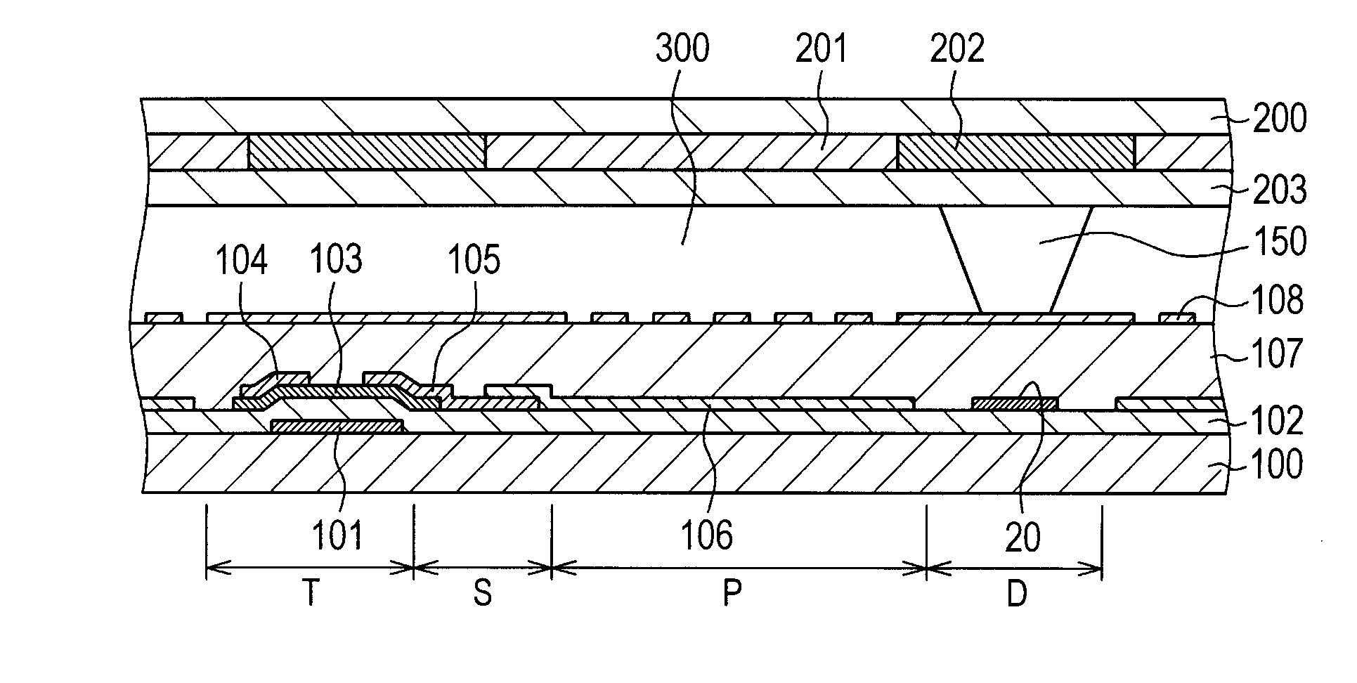
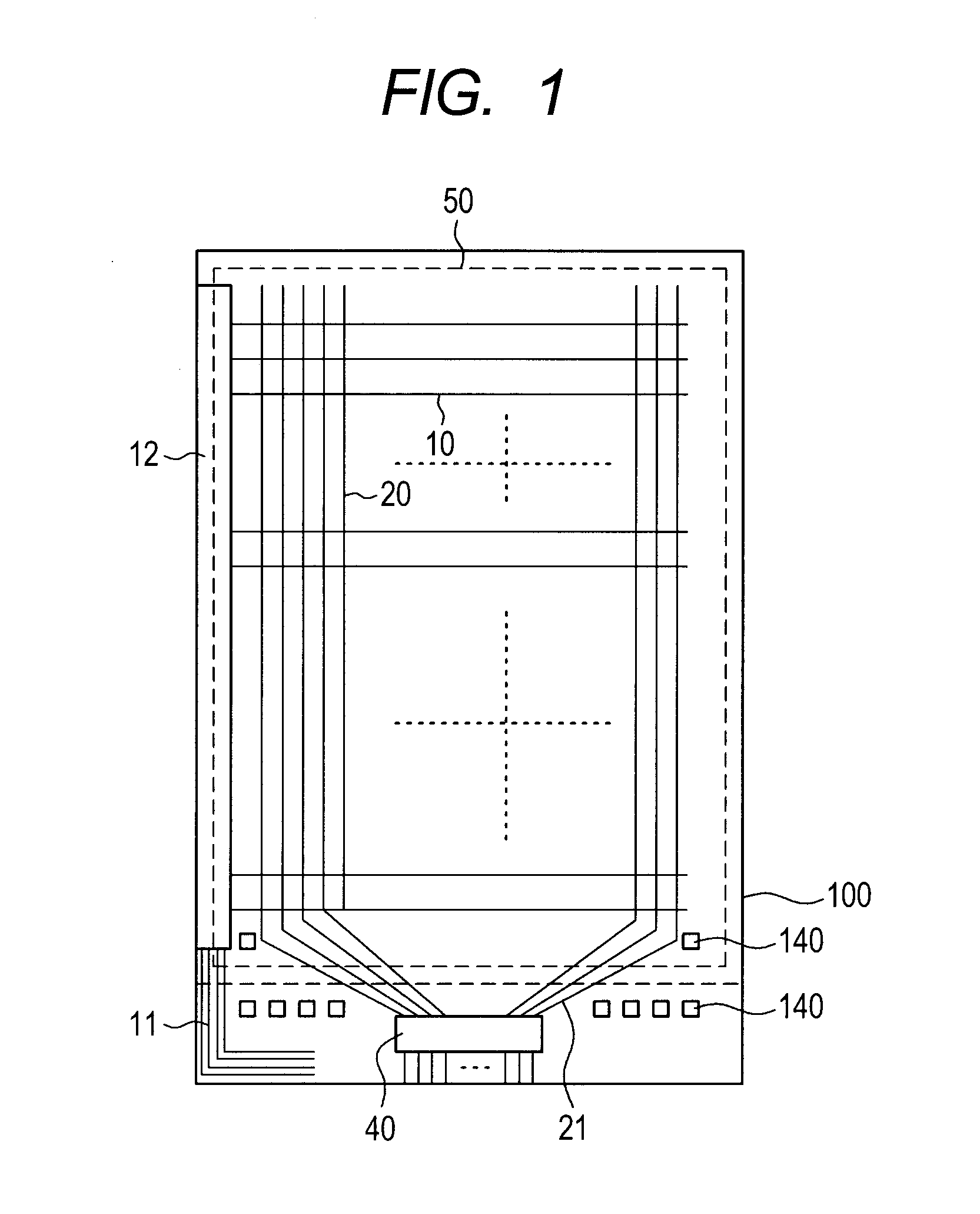
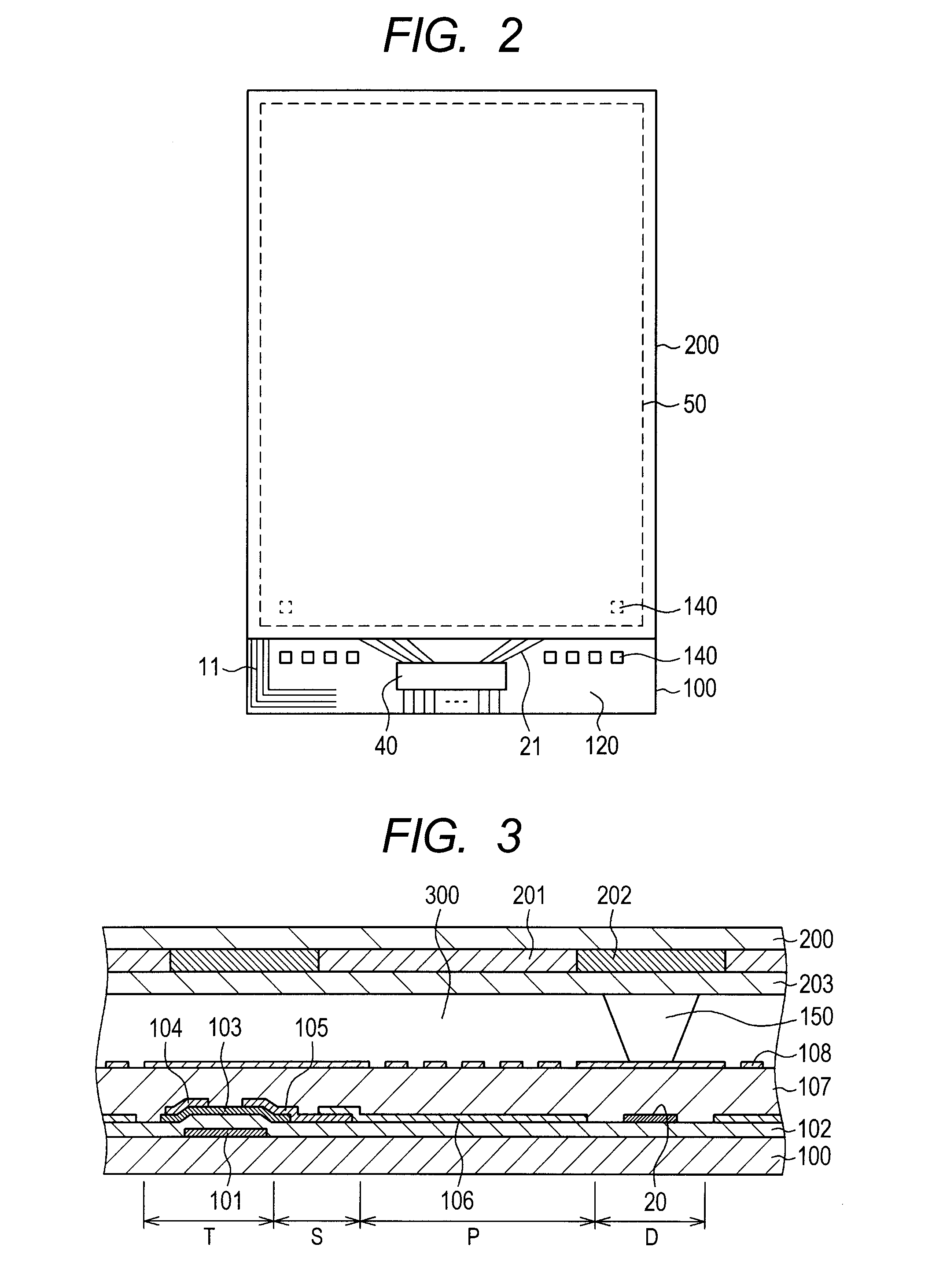
[0028]FIG. 1 is a plan view of a TFT substrate 100 according to the present invention. In FIG. 1, scan lines 10 extend in the horizontal direction and are arranged in the vertical direction in the display area. A scan line driving circuit 12 is formed on the left side of the TFT substrate 100. The scan lines 10 extend in the horizontal direction from the scan line driving circuit 12. Scan line driving circuit leaders 11 are formed in the scan line driving circuit to fetch signals from the outside. In FIG. 1, image signal lines 20 extend in the vertical direction and are arranged in the horizontal direction. Then, image signal line leaders 21 extend from the image signal lines 20 to an IC driver 40.
[0029]The peripheral area between the dashed lines and the end portion shown in FIG. 1 is a sealing portion 50. In FIG. 1, a mount 140 for a cylindrical spacer 150 formed in a counter substrate 200, not shown, is formed in the area where the lines are not present. In FIG. 1, this correspon...
second embodiment
[0041]In order to increase the productivity of liquid crystal display panels, a large number of liquid crystal display panels (liquid crystal cells) are formed in a mother substrate 1000 to simultaneously form a large number of liquid crystal cells. Thus, if the distance between the TFT substrate 100 and the counter substrate 200 in each liquid crystal cell is not properly provided in the state of the mother substrate 1000, this will appear as uneven gap of the product.
[0042]FIG. 7 is a schematic plan view of the structure to solve this problem. FIG. 7 shows the mother substrate 1000 in which a large number of liquid crystal cells are formed. The mother substrate 1000 is formed by bonding a mother TFT substrate in which a large number of TFT substrates 100 are formed, and a mother counter substrate in which a large number of counter substrates 200 are formed, by a mother substrate sealing material 500 as well as the sealing material 50 formed in each liquid crystal display panel.
[00...
third embodiment
[0050]A third embodiment is an example in which the cylindrical spacer 150 is formed on the TFT to maintain the distance between the TFT substrate 100 and the counter substrate 200 in the display area. In FIG. 11, in the display area, the cylindrical spacer 150 formed in the counter substrate 200 comes into contact above the TFT formed in the TFT substrate 100. In this case, the structure of the mount 140 within the sealing portion 50 shown in FIG. 1, has the gate electrode 101, the gate insulating film 102, the a-Si film 103, the source-drain layer 105, the inorganic passivation film 107, and the ITO forming the common electrode 108, in this order from the bottom in the counter substrate 200. Thus, the mount 140 shown in the right side of FIG. 11 has the same layer structure as that of the mount 140 shown in FIG. 1. Here, in the mount 140 shown in the right side of FIG. 11, the gate electrode 101, the source-drain electrode 105, and the ITO 108 are conductive films. These conductiv...
PUM
 Abstract
Description
Claims
Application Information
 - R&D Engineer
- R&D Manager
- IP Professional
- Industry Leading Data Capabilities
- Powerful AI technology
- Patent DNA Extraction
Browse by: Latest US Patents, China's latest patents, Technical Efficacy Thesaurus, Application Domain, Technology Topic, Popular Technical Reports.
© 2024 PatSnap. All rights reserved.Legal|Privacy policy|Modern Slavery Act Transparency Statement|Sitemap|About US| Contact US: help@patsnap.com


