
Grooved Tiles, Grooved Tile Assemblies and Related Methods

a technology of grooved tiles and grooves, applied in the field of tile, can solve the problems of laborious use of mosaic tiles, increased tile installation cost, and increased tile installation cost, and achieve the effect of easy ma

Inactive Publication Date: 2012-12-20
ESQUIVEL KRISANN
View PDF53 Cites 24 Cited by
  • Summary
  • Abstract
  • Description
  • Claims
  • Application Information

AI Technical Summary

Benefits of technology

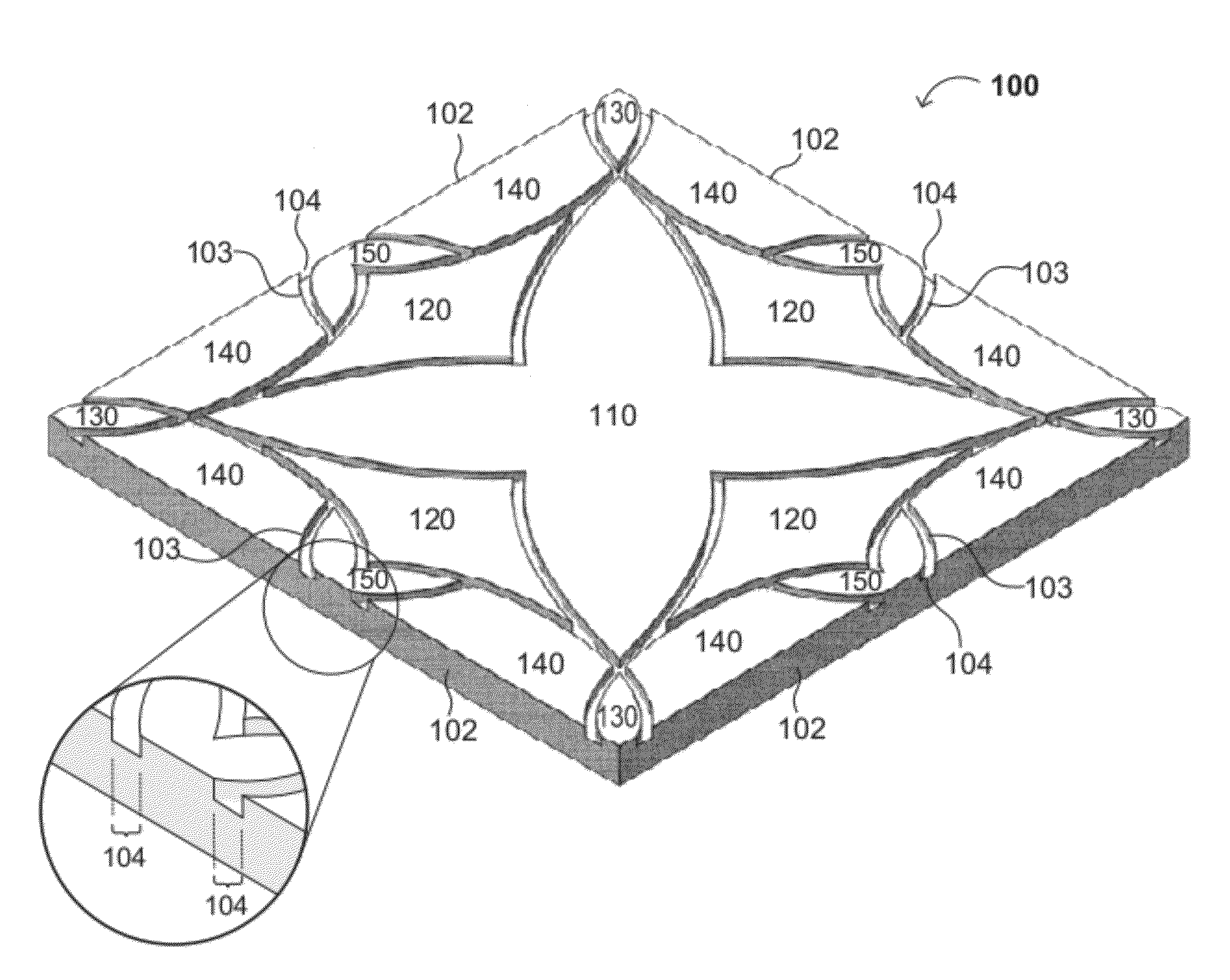
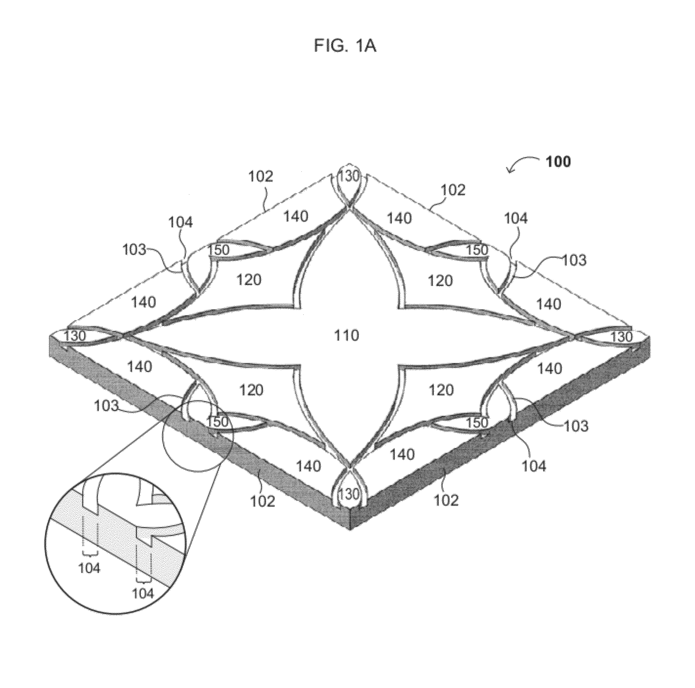
[0016]Embodiments of the present invention can advantageously provide grooved tiles having grooves that easily mate with the grooves in other identical or different grooved tiles when the intersection locations of adjacent tiles are aligned. Embodiments of the present invention can also advantageously provide tiles that give the appearance of being made of numerous smaller individual tiles, thus eliminating the need for separately placing smaller individual tiles and / or spacers between the tiles, or first backing the tiles with mesh, netting, or paper backing.

Problems solved by technology

Such careful placement requires additional time and adds to the cost of the tile installation.
However, such tiles typically include only straight score lines that intersect opposing edges of the tile, are generally limited to ceramics, and are usually scored after the ceramic tile has been glazed and / or cut for installation.
However, use of mosaic tiles (typically tiles smaller than 6 square inches) is labor intensive.
However, gluing tiles to mesh, netting, or paper backing requires one or more extra steps in the manufacturing and / or installation processes, thus increasing the cost of the tiles and of creating a design using small tiles.
Additionally, creativity may be limited because the small tiles are generally square (in lieu of other cut polygonal or curved shapes), and are placed in predetermined positions on the backing, generally creating a uniform grid of tiles.
The additional labor cost in setting the spacers may also increase the cost of the tile installation.

Method used


Image

  • Grooved Tiles, Grooved Tile Assemblies and Related Methods
  • Grooved Tiles, Grooved Tile Assemblies and Related Methods
  • Grooved Tiles, Grooved Tile Assemblies and Related Methods

Examples


Embodiment Construction

[0043]Reference will now be made in detail to various embodiments of the invention, examples of which are illustrated in the accompanying drawings. While the invention will be described in conjunction with the following embodiments, it will be understood that the descriptions are not intended to limit the invention to these embodiments. On the contrary, the invention is intended to cover alternatives, modifications, and equivalents that may be included within the spirit and scope of the invention as defined by the appended claims. Furthermore, in the following detailed description, numerous specific details are set forth in order to provide a thorough understanding of the present invention. However, it will be readily apparent to one skilled in the art that the present invention may be practiced without these specific details. In other instances, well-known methods, procedures and components have not been described in detail so as not to unnecessarily obscure aspects of the present ...


PUM

PropertyMeasurementUnit
Fractionaaaaaaaaaa
Fractionaaaaaaaaaa
Sizeaaaaaaaaaa

Abstract

Grooved tiles, grooved tile assemblies, methods of manufacturing grooved tiles, and methods of forming grooved tile assemblies are disclosed. The tiles of the present invention include grooves or recesses in the top surface that form one or more complete patterns and / or partial patterns, and that may intersect with one or more edges of the tile. The grooves of one tile can advantageously mate with the grooves of other identical or different grooved tiles when the intersection locations of adjacent tiles are aligned. In addition, the grooved tiles can provide the appearance of including numerous smaller individual tiles, thus eliminating the need for separately placing spacers between the tiles or first backing the tiles with mesh, netting, or paper backing prior to or during installation.

Description

CROSS REFERENCE TO RELATED APPLICATION[0001]This application claims the benefit of U.S. Provisional Patent Application No. 61 / 497,396, filed Jun. 15, 2011.FIELD OF THE INVENTION[0002]The present invention generally relates to the field of tiles. More specifically, embodiments of the present invention pertain to grooved tiles, grooved tile assemblies, methods of manufacturing grooved tiles and methods of forming grooved tile assemblies.DISCUSSION OF THE BACKGROUND[0003]Tiles are used for covering a wide variety of objects and surfaces for indoor and outdoor uses such as floors, walls, showers, pools and surrounding decks, tables, countertops, backsplashes, cabinets, fireplaces and other surfaces or objects. Tiles may be functional (i.e., to protect the surface that is covered) or may be used for strictly decorative purposes, such to create wall, floor, tabletop or ceiling designs or mosaics. Tile materials in various sizes, shapes, and colors may be assembled to create a tile unit or...

Claims


Application Information

Patent Timeline
IPC IPC(8): E04F13/072E04G21/14B26D3/06B44F3/00
CPCB28D1/18Y10T409/303752B28D1/30Y10T83/0304
Inventor ESQUIVEL, KRISANN
Owner ESQUIVEL KRISANN
Learn More