Method and device for measuring motion error of linear stage

a technology of motion error and linear stage, which is applied in the direction of measurement devices, instruments, interferometers, etc., can solve the problems of entanglement stage errors, difficult installation and operation of devices, providing installation errors, etc., and achieve the effect of accurate measurement of motion errors

Active Publication Date: 2012-12-13
GWANGJU INST OF SCI & TECH
View PDF2 Cites 4 Cited by
  • Summary
  • Abstract
  • Description
  • Claims
  • Application Information

AI Technical Summary

Benefits of technology

[0011]Therefore, the present invention is aimed at providing a method and device for measuring motion errors of a linear stage, which enable accurate measurement of the motion errors in the linear stage in real time through an integrated device.

Problems solved by technology

Although such a linear stage is configured to perform linear motion, the linear stage entails various errors including errors in a moving direction thereof.
For the ultra-precision linear stage, such errors cause significant problems, and thus it is very important to ascertain precision of the linear stage based on measurement of such errors.
In a conventional measurement method, however, various measuring devices are used at the same time, making it difficult to install and operate the devices and providing installation errors.
Furthermore, the conventional method has difficulty ascertaining accuracy of measured values, irrespective of high likelihood of errors.
Moreover, since the laser interferometer and the autocollimator applied to the conventional measurement method are very expensive, purchase of all of these devices entails a significant economic burden.

Method used


Image

  • Method and device for measuring motion error of linear stage
  • Method and device for measuring motion error of linear stage
  • Method and device for measuring motion error of linear stage

Examples


Embodiment Construction

[0029]Exemplary embodiments of the present invention will now be described in detail with reference to the accompanying drawings. It should be noted that like components will be denoted by like reference numerals throughout the specification and the drawings. In addition, description of details apparent to those skilled in the art will be omitted for clarity. Further, it should be understood that the present invention is not limited to the following embodiments and may be embodied in different ways by those skilled in the art without departing from the scope of the present invention.

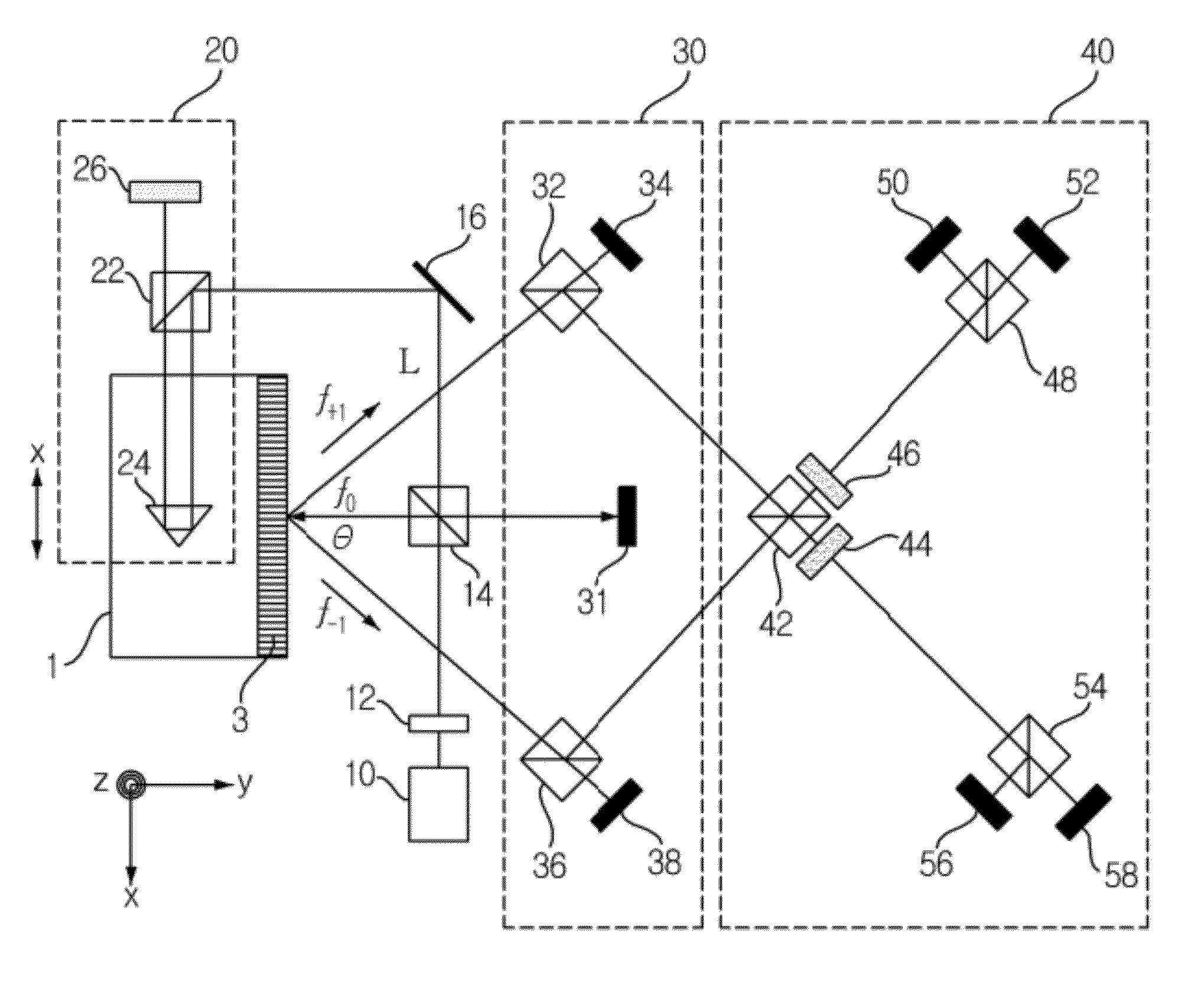
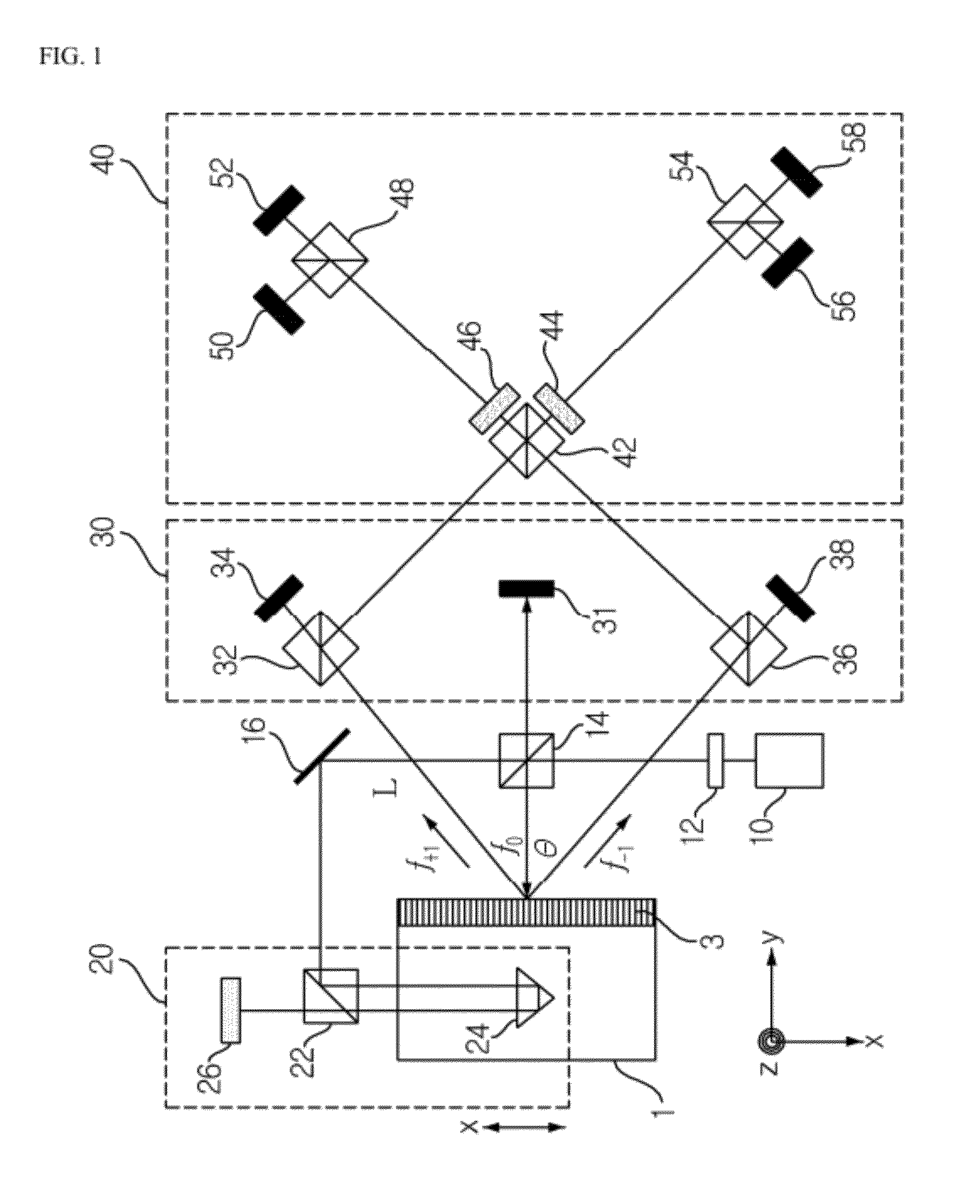
[0030]FIG. 1 is a diagram of a device for measuring motion errors of a linear stage in accordance with one exemplary embodiment of the present invention.

[0031]A linear stage 1 may be linearly operated in various ways, including ball-screw operation, linear motor operation, piezoelectric transducer operation, and the like. For enhanced precision in linear operation of the linear stage 1, it is necessary t...


PUM


Abstract

Measurement of motion errors of a linear stage is performed to enable accurate measurement of motion errors in linear directions and a rotational direction in the linear stage using a diffraction grating. A first beam splitter splits a laser beam emitted from a light emitting unit. A first measurement unit measures a unidirectional linear motion error of the linear stage using one laser beam component split by the first beam splitter and a second measurement unit measures an angular motion error and another unidirectional linear motion of the linear stage error using a diffracted beam component obtained by diffracting another laser beam component split by the first beam splitter through the diffraction grating. A third measurement unit circularly polarizes the beam component diffracted through the diffraction grating to measure a third unidirectional linear motion error of the linear stage.

Description

CROSS-REFERENCE TO RELATED APPLICATION[0001]This application claims the benefit under 35 U.S.C. §119 of Korean Patent Application No. 10-2011-0056473, filed on Jun. 10, 2011 in the Korean Intellectual Property Office, the entirety of which is incorporated herein by reference.BACKGROUND[0002]1. Technical Field[0003]The present invention relates to a method and device for measuring motion errors of a linear stage. More particularly, the present invention relates to a method and device for measuring motion errors of a linear stage, which can accurately measure motion errors in linear and rotational directions of the linear stage.[0004]2. Description of the Related Art[0005]With industrial development in recent years, products and components are increasingly reduced in size and augmented with new functions, and demand for production techniques capable of providing nano-scale precision is present with the development of IT, BT and NT fields. Among production systems developed to cope wit...

Claims


Application Information

Patent Timeline
Patent Type & Authority Applications(United States)
IPC IPC(8): G01B9/02
CPCG01B9/02027G01B2290/70G01B2290/45G01B2290/30G01B9/02081G01B11/00
Inventor LEE, SUN-KYULEE, CHABUMKIM, GYU HA
Owner GWANGJU INST OF SCI & TECH
Why Eureka
Try Eureka