
Electrostatic precipitator

Active Publication Date: 2012-12-13
SAMSUNG ELECTRONICS CO LTD
View PDF17 Cites 22 Cited by
  • Summary
  • Abstract
  • Description
  • Claims
  • Application Information

AI Technical Summary

Benefits of technology

[0033]The intermediate partition may include a rim portion, a reinforcing portion to shape the intermediate partition into a lattice form and to increase the strength of the rim portion, and second electrode support ele

Problems solved by technology

However, once captured dust has been accumulated on surfaces of the electrodes, electric current momentarily may flow from the conductive electrodes to the accumulated dust, causing insulation breakdown or discharge between the electrodes.
In the case of coating all the high-voltage and low-voltage electrodes of the collector with plastic resin, although it may be effective in terms of preventing insulation breakdown, the high-voltage electrode coated with plastic resin exhibits deterioration in surface potential and the

Method used


Image

  • Electrostatic precipitator
  • Electrostatic precipitator
  • Electrostatic precipitator

Examples


Example

[0051]Reference will now be made in detail to the embodiments of the present disclosure, examples of which are illustrated in the accompanying drawings, wherein like reference numerals refer to like elements throughout.

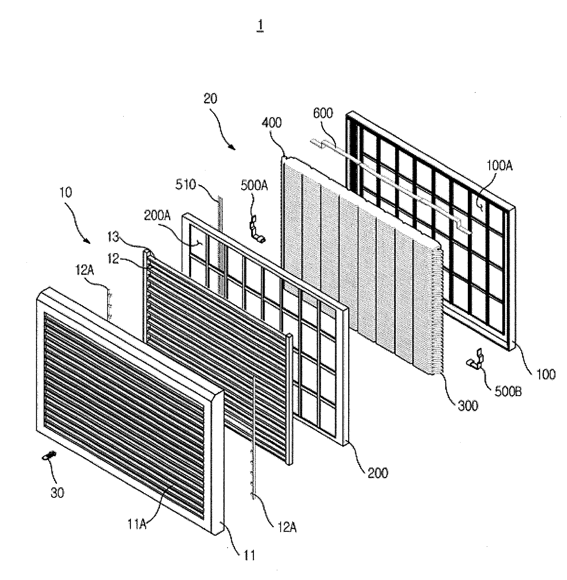
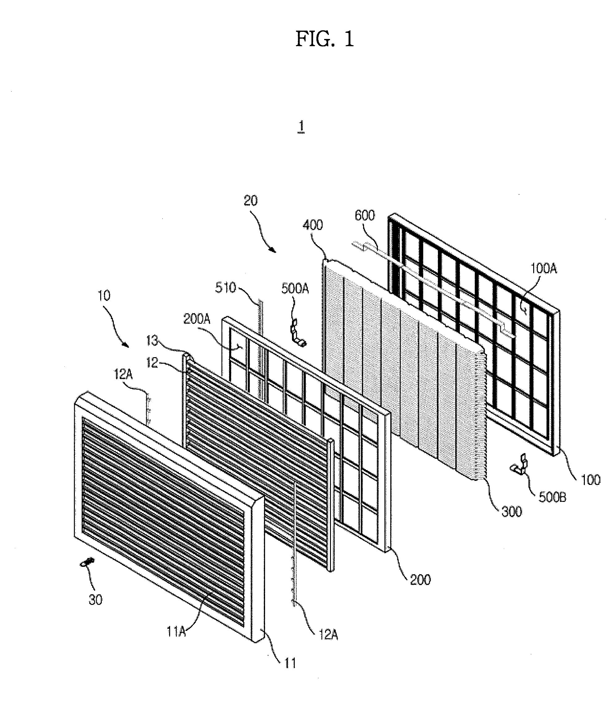
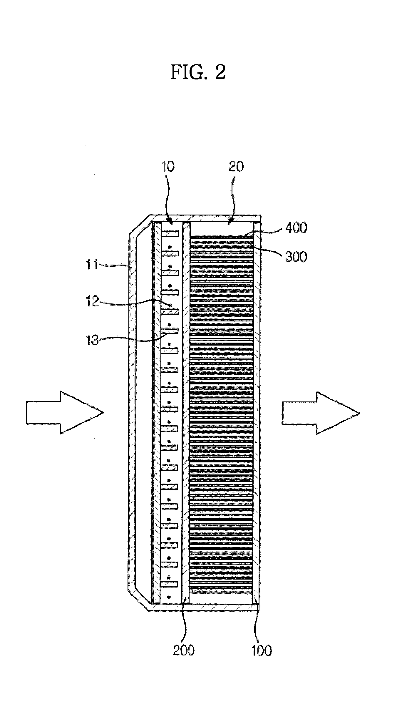
[0052]FIG. 1 is an exploded perspective view illustrating an electrostatic precipitator according to an embodiment of the present disclosure, and FIG. 2 is a side view of the electrostatic precipitator according to the embodiment of the present disclosure.

[0053]As illustrated in FIGS. 1 and 2, the electrostatic precipitator 1 according to the embodiment of the present disclosure includes a charger 10 to ionize dust particles in air, and a collector 20 to collect the dust particles charged by the charger 10.

[0054]The charger 10 may include a charger case 11 having suction slots 11A, a discharge electrode 12 which serves as a positive pole via a discharge-electrode power-connection terminal 12A, and a counter electrode 13 which is vertically spaced apart from the discha...


PUM


Abstract

An electrostatic precipitator including a charger to charge dust particles in air and a collector to collect the dust particles. The collector includes a collector case including high-voltage electrodes, to which high-voltage is applied, low-voltage electrodes alternately stacked with the high-voltage electrodes so as to be grounded, and first electrode support elements to support the high-voltage and low-voltage electrodes with a distance therebetween. The first electrode support elements include electrode contact terminals to support extreme edge portions of the high-voltage and low-voltage electrodes. The high-voltage and low-voltage electrodes are formed of a conductive material, or a non-conductive material, the surface of which is subjected to conductive treatment. The electrode contact terminals for the high-voltage electrodes are formed of a semiconductive material. Accordingly, it is possible to maintain a constant distance between the electrodes and to prevent insulation breakdown without deterioration in the performance of the collector.

Description

CROSS-REFERENCE TO RELATED APPLICATIONS[0001]This application claims the benefit of Korean Patent Application No. 10-2011-0055953, filed on Jun. 10, 2011 in the Korean Intellectual Property Office, the disclosure of which is incorporated herein by reference.BACKGROUND[0002]1. Field[0003]Embodiments of the present disclosure relate to an electrostatic precipitator having manufacturability at lower cost and high precipitation efficiency.[0004]2. Description of the Related Art[0005]Generally, an electrostatic precipitator is installed in electronic appliances, such as, e.g., an air conditioner and air purifier, as well as precipitation facilities for buildings and industrial uses. The electrostatic precipitator serves to purify air by collecting contaminants, such as dust, etc., contained in the air.[0006]Most electrostatic precipitators employ a two-stage electrostatic precipitation method using a charger and a collector separated from each other. In the most general configuration, th...

Claims


Application Information

Patent Timeline
IPC IPC(8): B03C3/47
CPCB03C3/08B03C3/12B03C3/41B03C2201/10B03C3/60B03C3/86B03C2201/04B03C3/47B03C3/00B03C3/02B03C3/40B03C3/66
Inventor NOH, HYONG SOOYASUHIKO, KOCHIYAMAYUN, SO YOUNG
Owner SAMSUNG ELECTRONICS CO LTD
Learn More