
Wireless sound transmission system and method using improved frequency hopping and power saving mode

a technology of frequency hopping and power saving mode, applied in the direction of power management, sustainable buildings, and restrictions, to achieve the effect of reducing power consumption, further power consumption reduction, and reducing power consumption

Inactive Publication Date: 2012-12-06
SONOVA AG
View PDF5 Cites 55 Cited by
  • Summary
  • Abstract
  • Description
  • Claims
  • Application Information

AI Technical Summary

Benefits of technology

The invention is a sound transmission system that uses a digital audio link and is relatively interference resistant. It allows for fast synchronization with low power requirements on the receiver side. The system is well-suited for multiple receiver units and can easily be used with different types of receivers. The invention uses slow frequency hopping for transmission and passive synchronization in a duty cycling mode to achieve relatively fast synchronization and low power consumption. The system also includes a hopping sequence ID that is allocated to each frame and is used to calculate the frequency at which the beacon packet of the next frame is to be received. The receiver units sleep during times when no data packets are expected and wake up a given guard time before the expected arrival of an audio packet. This further reduces power consumption. Overall, the invention provides a more efficient and effective sound transmission system.

Problems solved by technology

The resulting improvements of signal level and SNR in the listener's ear are recognized as the primary benefits of FM radio systems, as hearing-impaired individuals are at a significant disadvantage when processing signals with a poor acoustical SNR.

Method used


Image

  • Wireless sound transmission system and method using improved frequency hopping and power saving mode
  • Wireless sound transmission system and method using improved frequency hopping and power saving mode
  • Wireless sound transmission system and method using improved frequency hopping and power saving mode

Examples


Embodiment Construction

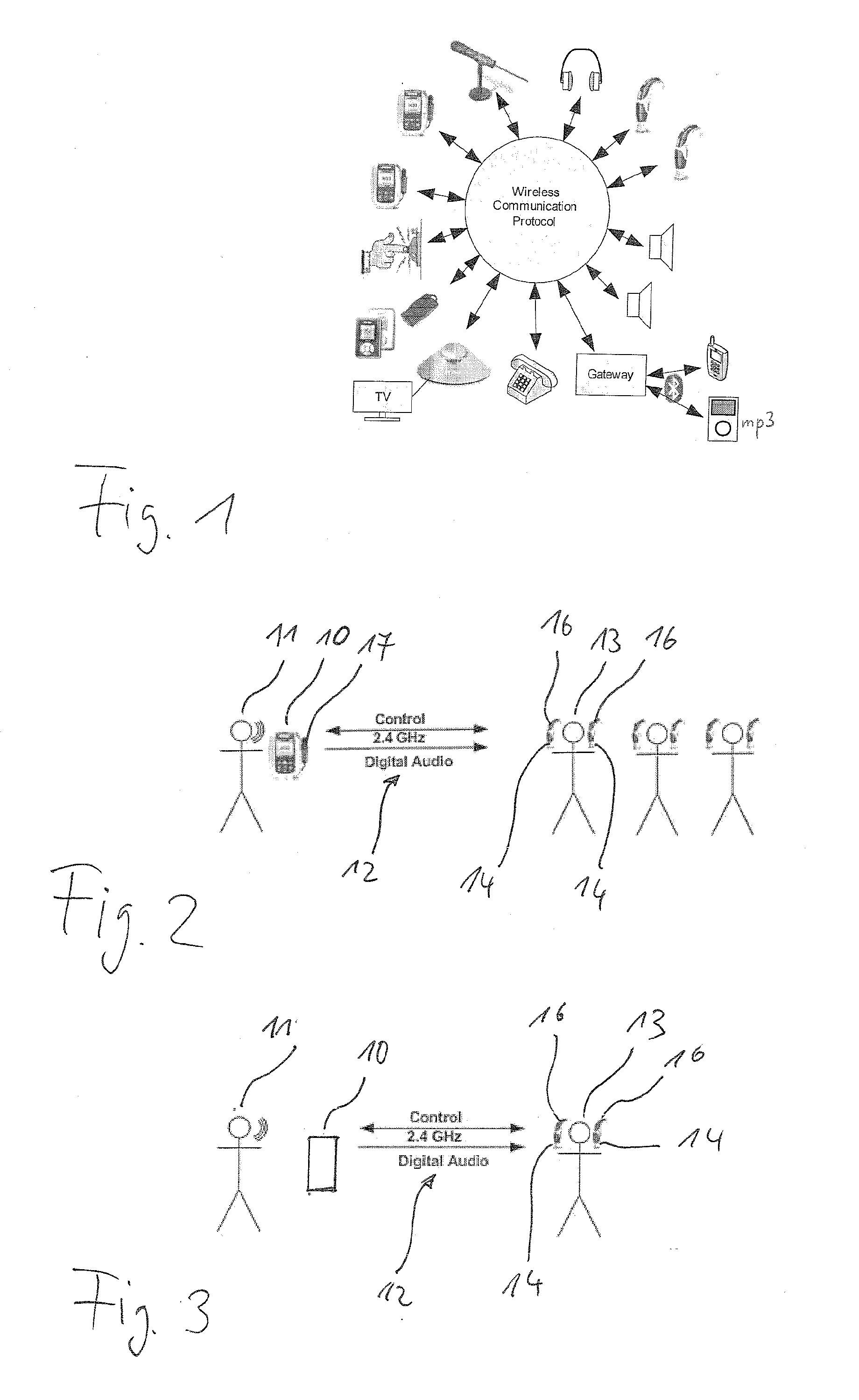
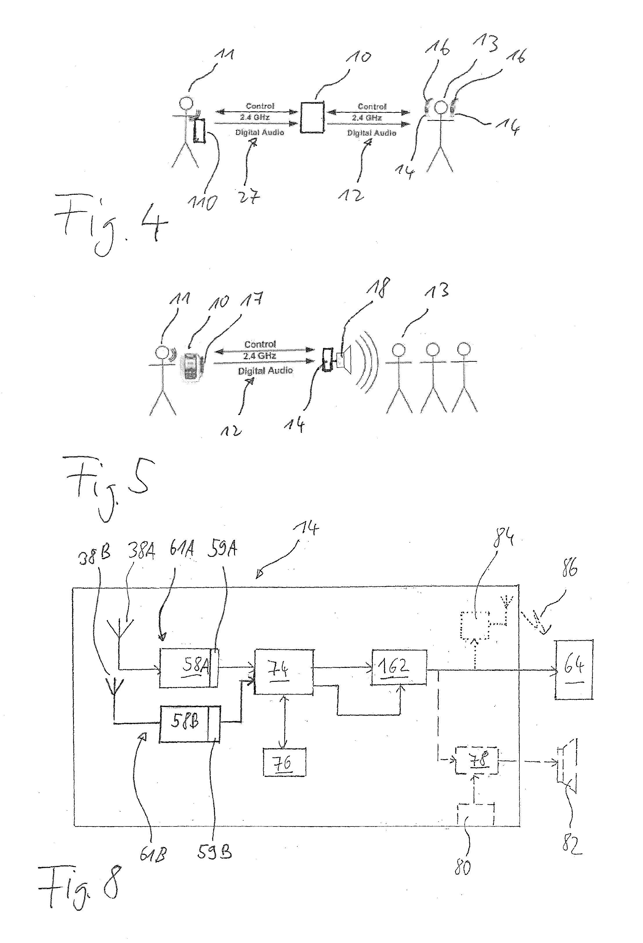
[0055]The present invention relates to a system for providing hearing assistance to at least one user, wherein audio signals are transmitted from an audio signal source via a wireless digital audio link, using a transmission unit comprising a digital transmitter, to at least one receiver unit, from which the audio signals are supplied to means for stimulating the hearing of the user, typically a loudspeaker.

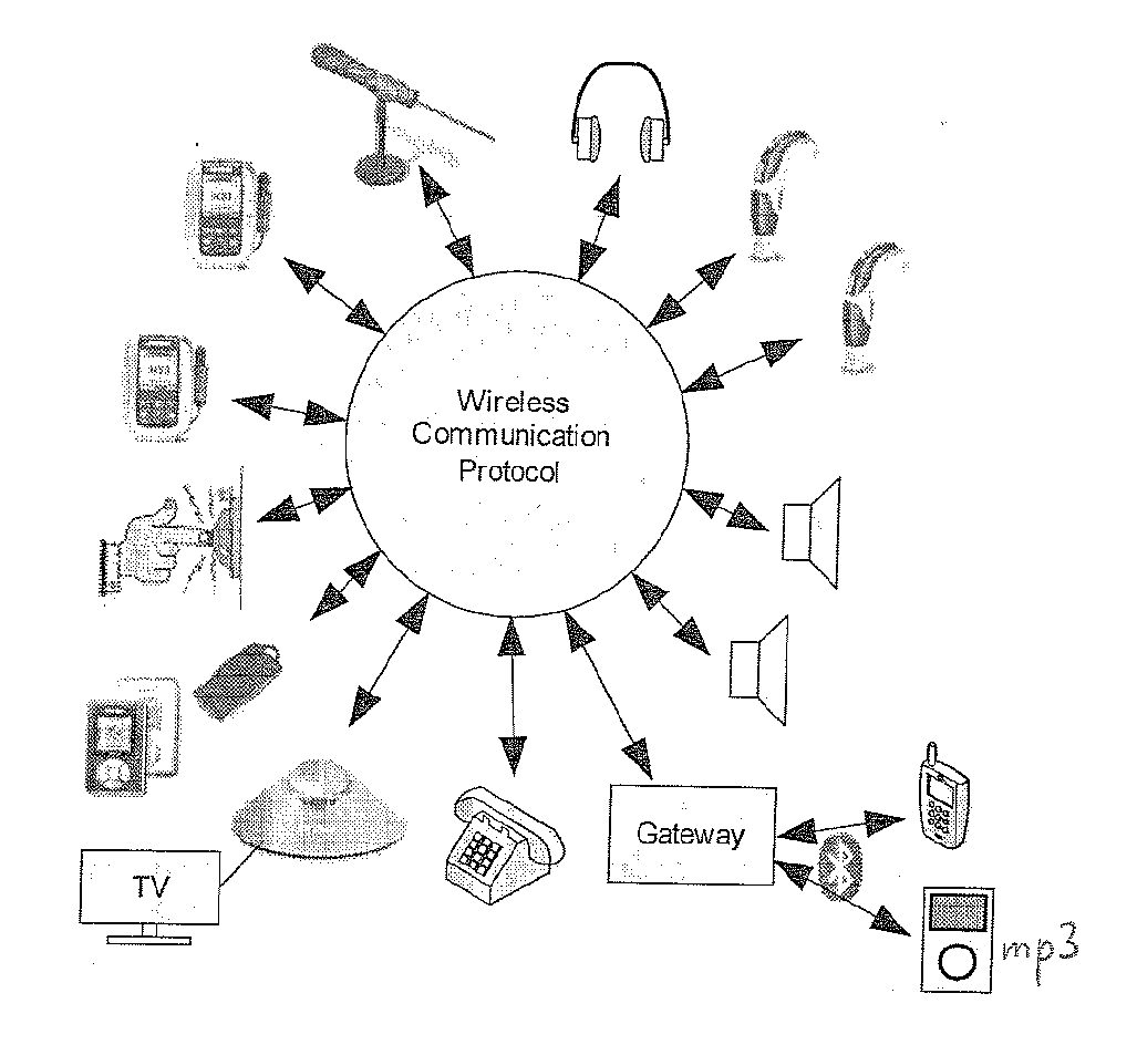
[0056]As shown in FIG. 1, the device used on the transmission side may, for example, be a wireless microphone used by a speaker in a room for an audience; an audio transmitter having an integrated or a cable-connected microphone which are used by teachers in a classroom for hearing-impaired pupils / students; an acoustic alarm system, like a door bell, a fire alarm or a baby monitor; an audio or video player; a television device; a telephone device; a gateway to audio sources like a mobile phone, music player; etc. The transmission devices include body-worn devices as well as fixed...


PUM


Abstract

A system for providing sound to at least one user, having an audio signal source; a transmission unit with a digital transmitter which wirelessly transmits audio signals digitally as data packets, at least one receiver unit with at least one digital receiver and a mechanism for stimulating user hearing. Each data packet is transmitted in a separate slot of a TDMA frame at a different frequency according to a frequency hopping sequence, the first slot of each frame being a beacon packet containing hopping frequency information. Each receiver unit passively synchronizes to the transmission unit without sending messages to it by periodically waking to listen for the beacon packets, the listening frequency channel changing according to a fixed scheme from listening period to listening period, the beacon listening periodicity differing from the beacon transmission periodicity, each receiver unit switching into a synchronized mode after successful receipt of a beacon packet.

Description

BACKGROUND OF THE INVENTION[0001]1. Field of the Invention[0002]The invention relates to a system and a method for providing sound to at least one user, wherein audio signals from an audio signal source, such as a microphone for capturing a speaker's voice, are transmitted via a wireless link to a receiver unit, such as an audio receiver for a hearing aid, from where the audio signals are supplied to means for stimulating the hearing of the user, such as a hearing aid loudspeaker.[0003]2. Description of Related Art[0004]Presently, in such systems, the wireless audio link usually is an FM (frequency modulation) radio link. According to a typical application of such wireless audio systems, the receiver unit is connected to or integrated into a hearing instrument, such as a hearing aid, with the transmitted audio signals being mixed with audio signals captured by the microphone of the hearing instrument prior to being reproduced by the output transducer of the hearing instrument. The b...

Claims


Application Information

Patent Timeline
Patent Type & Authority Applications(United States)
IPC IPC(8): G06F17/00
CPCH04R25/554H04W48/16Y02B60/50H04W84/18H04W52/0229Y02D30/70
Inventor EL-HOIYDI, AMRE
Owner SONOVA AG
Learn More