
Control unit and driving apparatus using the same

a technology of control unit and driving apparatus, which is applied in the direction of control/drive circuit, dynamo-electric machines, structural associations, etc., can solve the problems of adverse influence on other electrical parts and/or components, such as connectors, and achieve the effect of suppressing the propagation of magnetic fields and suppressing the propagation of noise of switching devices

Inactive Publication Date: 2012-12-06
DENSO CORP
View PDF0 Cites 34 Cited by
  • Summary
  • Abstract
  • Description
  • Claims
  • Application Information

AI Technical Summary

Benefits of technology

[0009]According to the above features, propagation of the magnetic field, which is generated by the electric current flowing through the switching devices and the wiring portions, can be suppressed. In other words, it is possible to suppress that the magnetic field (generated by the electric current flowing through the switching devices and the wiring portions) may affect adverse influences on other parts and / or components. Therefore, propagation of noises of the switching devices can be suppressed.

Problems solved by technology

In the above prior art, a magnetic field, which is generated by electric current flowing through the switching devices, may affect adverse influence on other electrical parts and / or components, such as connectors.

Method used


Image

  • Control unit and driving apparatus using the same
  • Control unit and driving apparatus using the same
  • Control unit and driving apparatus using the same

Examples


first embodiment

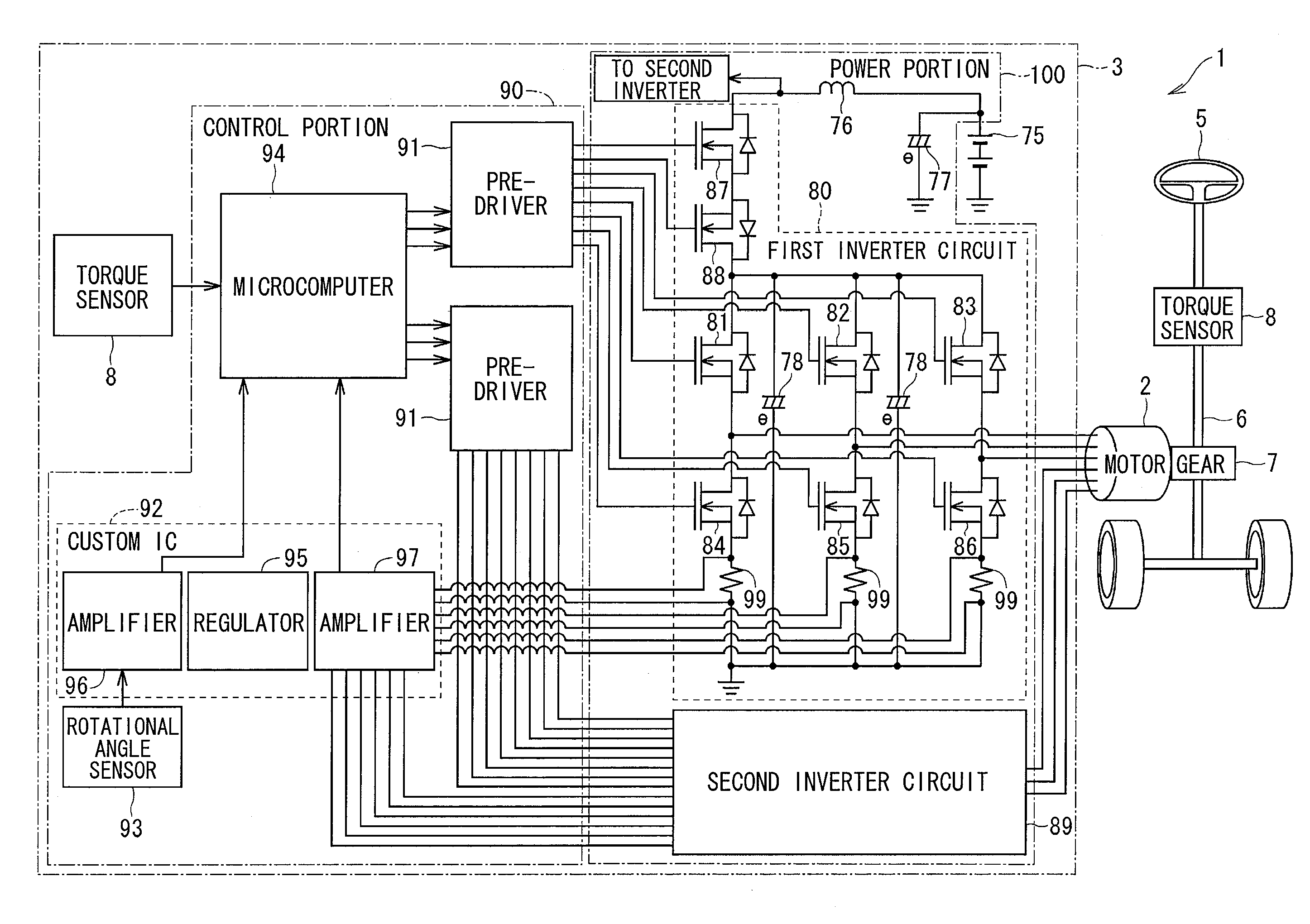
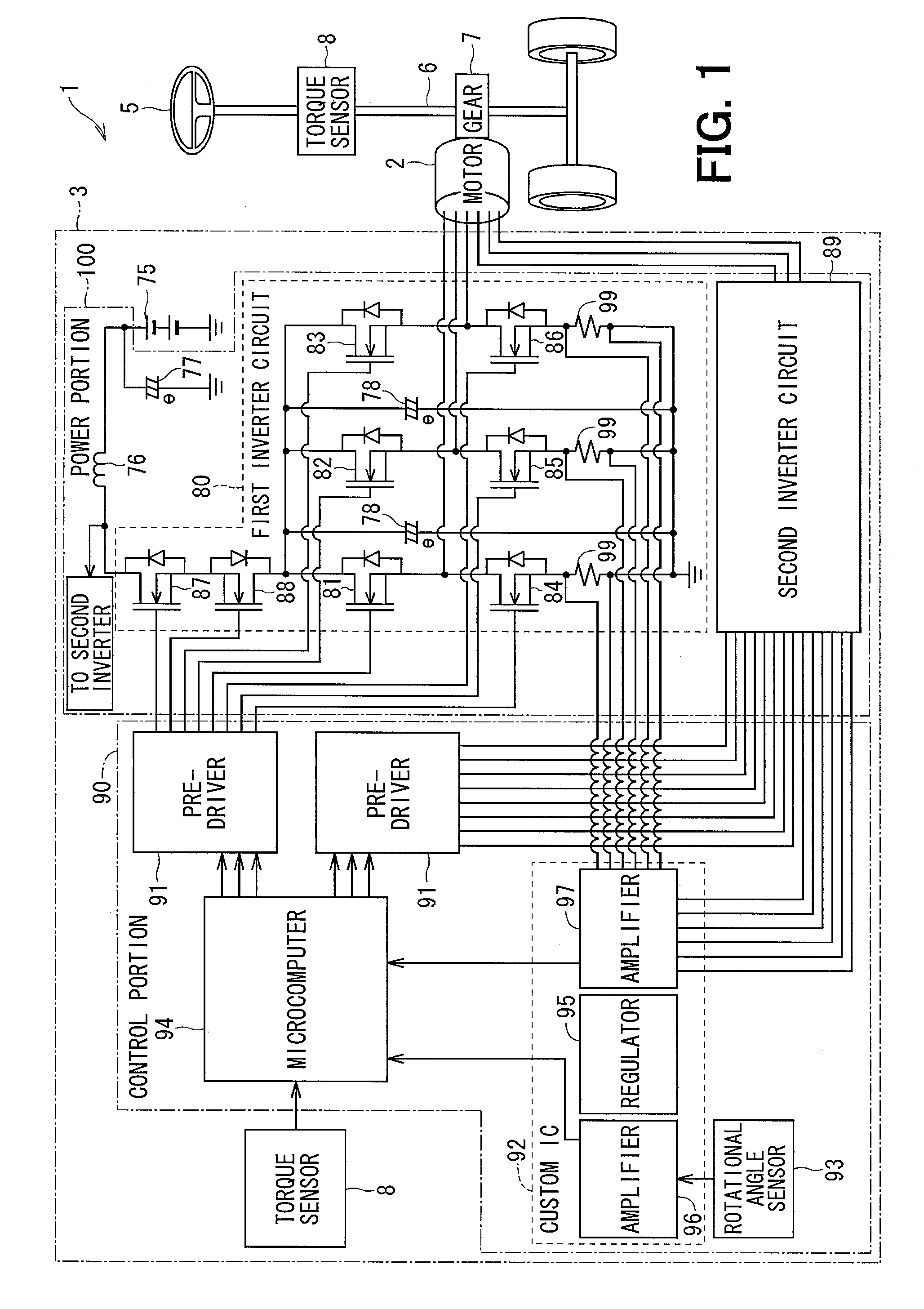
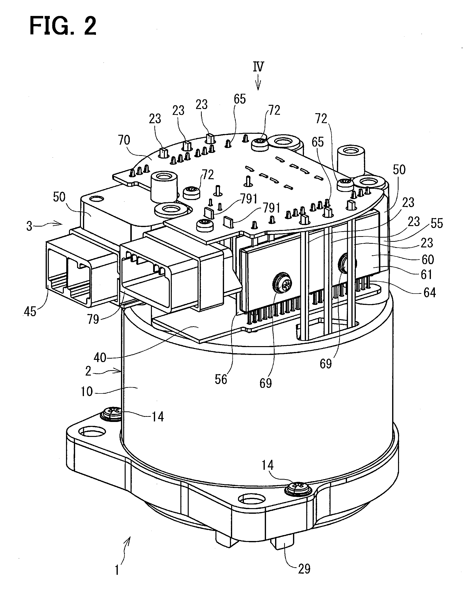
[0020]A driving apparatus 1 of a first embodiment of the present disclosure will be explained with reference to FIGS. 1 to 7. The driving apparatus 1 is applied to an electrical power steering device (EPS) for a vehicle. The driving apparatus 1 is composed of an electric motor 2 and a control unit 3.

[0021]An electrical configuration of the EPS will be explained with reference to FIG. 1.

[0022]As shown in FIG. 1, the driving apparatus 1 generates a rotational torque at a column shaft 6, which is a rotational shaft for a steering wheel 5 of a vehicle, via a gear of a gear box 7 provided in the column shaft 6, so as to assist a steering operation by the steering wheel 5. More in detail, when the steering wheel 5 is operated by a vehicle driver, a steering torque generated in the column shaft 6 is detected by a torque sensor 8 and information of a vehicle speed is obtained from CAN (Controller Area Network: not shown), so as to assist the steering operation of the steering wheel 5 by the...

second embodiment

[0089]A driving apparatus according to a second embodiment of the present disclosure will be explained with reference to FIG. 8.

[0090]As shown in FIG. 8, an inclined surface 57 and a vertical surface 58 are formed at a radial-inside surface of each heat receiving portion 55 of the heat sink 50. The inclined surface 57 is inclined with respect to the rotational axis 0 of the electric motor 2 and corresponds to the parallel surface 54 of the first embodiment. The vertical surface 58 is arranged to be in parallel to the rotational axis 0 of the electric motor 2. Each of the power modules 60 is arranged at the inclined surface 57 so as to be in parallel to the inclined surface 57. The power terminals 65 are arranged to be in parallel to the vertical surfaces 58.

[0091]The second embodiment has the same advantages to the first embodiment.

Further Modifications

[0092]In the above embodiments, the power terminals 65 (the wiring portions) of the switching devices and the power-output terminals...


PUM


Abstract

Power terminals of power modules are magnetically coupled to power-output terminals and power-input terminals. A heat sink has parallel surfaces, which are in parallel to the power modules and the power terminals. A magnetic field, which is generated by electric current flowing through switching devices and the power terminals, is cancelled by a magnetic field, which is generated by eddy current flowing in the heat sink.

Description

CROSS REFERENCE TO RELATED APPLICATION[0001]This application is based on Japanese Patent Application No. 2011-120272 filed on May 30, 2011, the disclosure of which is incorporated herein by reference.TECHNICAL FIELD[0002]The present invention relates to a control unit and a driving apparatus using the same for driving and controlling an operation of an electric motor.BACKGROUND[0003]A three-phase electric motor is known in the art, according to which the electric motor is driven to rotate when three-phase alternating current is supplied thereto.[0004]In a case that a power source for the three-phase electric motor is a direct-current power source having a predetermined voltage, it is necessary to provide a control unit having multiple switching devices, according to which current supply to stator coils is switched over so that stator-coil currents of different phases are supplied to respective stator coils (for example, three-phase coils). For example, switching devices are arranged...

Claims


Application Information

Patent Timeline
IPC IPC(8): H05K9/00
CPCH02K11/0073H02K3/50H02K2203/03H02K11/33
Inventor MASUZAWA, TAKASHIYAMASAKI, MASASHITAKI, HIROSHI
Owner DENSO CORP
Learn More