
Electroconductive endless belt

a technology of electroconductive and endless belts, applied in the direction of instruments, electrographic process apparatus, optics, etc., can solve the problems of large and expensive apparatus, inability to obtain high-quality images, and affect the transfer efficiency, so as to achieve uniform image, reduce cost, and avoid local unevenness

Inactive Publication Date: 2012-11-29
BRIDGESTONE CORP
View PDF3 Cites 9 Cited by
  • Summary
  • Abstract
  • Description
  • Claims
  • Application Information

AI Technical Summary

Benefits of technology

[0032]According to the present invention, by having the above-mentioned constitution, an electroconductive endless belt by which a good image with uniformity and without local unevenness can be obtained at a lower cost can be attained.

Problems solved by technology

This method enables a relatively compact apparatus configuration; however, it has a problem in that a high quality image cannot be obtained since gradation control is extremely difficult.
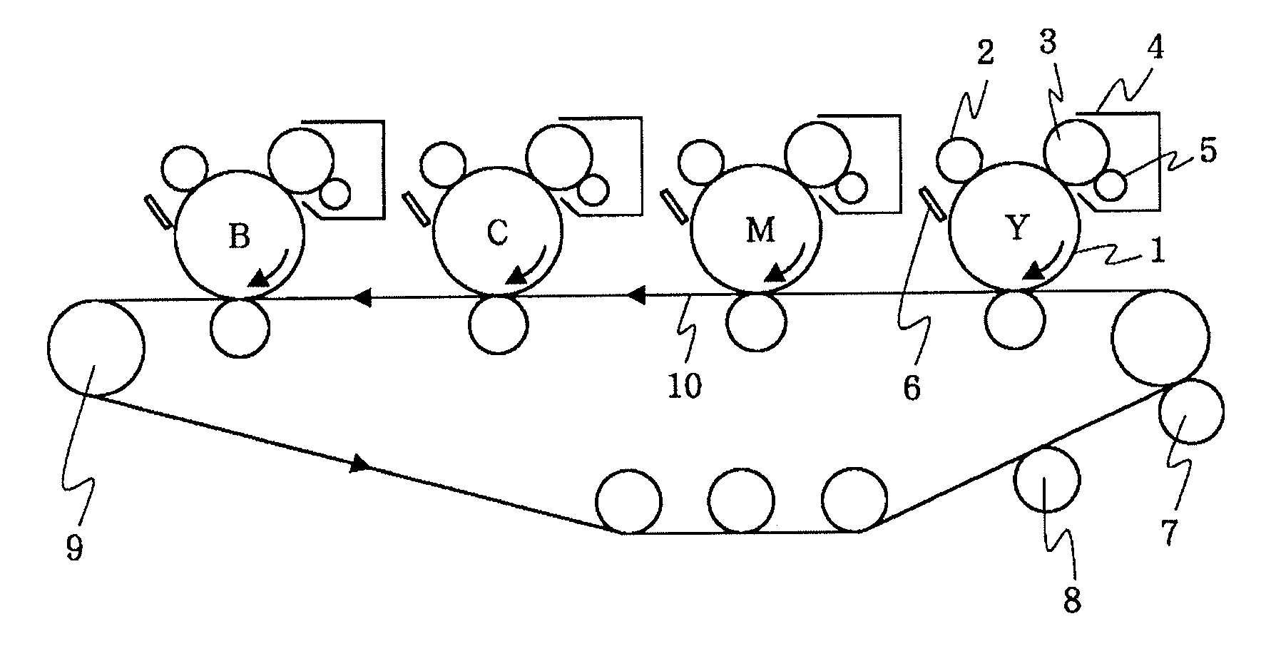
This method provides a good quality image; however, the apparatus is large and expensive since the four photoconductor drums, each of which has a charging mechanism and a developing mechanism, have to be configured in a line.
However, such resistive belt has disadvantages in that the transfer efficiency is affected by environmental variations as the resistance value varies depending on the environmental variations, and that it is likely to be affected by the thickness and width of the printing sheet.
A disadvantage of such dielectric belt is that charges are accumulated from repeated transfers, thereby increasing the transfer voltage.
This method yields an image having a relatively high quality; however, in cases where the recording medium is a thick paper such as a postcard, since lapping of such recording medium around the transfer drum is difficult, this method has a problem in that the type of the recording medium is limited.

Method used


Image

  • Electroconductive endless belt
  • Electroconductive endless belt
  • Electroconductive endless belt

Examples


examples

[0119]The present invention will now be described in more detail by way of Examples thereof.

examples 1 to 9

, Comparative Examples 1 to 6

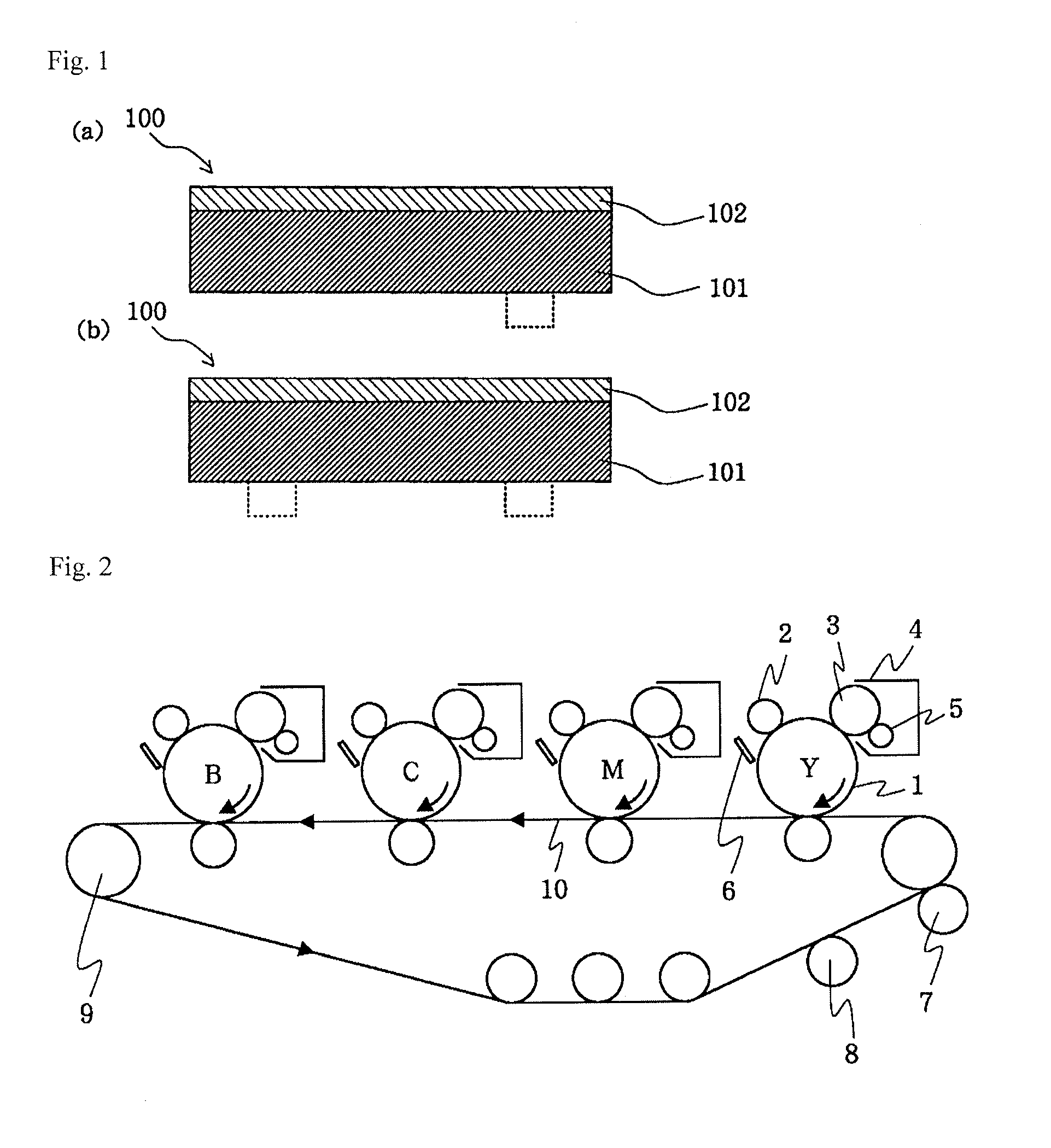
[0120]Electroconductive endless belts of each of Examples and Comparative Examples were produced in accordance with the formulations shown in Tables 6 to 8. Specifically, the blend components of belt substrate listed in each of the Tables were melt-kneaded by a biaxial kneader and the thus kneaded mixture was extruded using a circular die to produce a base layer 101 having an inner diameter of 220 mm and a thickness of 100 μm and a width of 250 mm. Thereafter, a solvent coating liquid for a resin layer which was produced by using materials to be added shown in each of the Tables using methyl ethyl ketone as a solvent is coated on the base layer 101 using a spray such that the film thickness thereof after drying was 2 μm. An electroconductive endless belt 100 was obtained by, while rotating the coated belt 100, irradiating ultraviolet at a luminance of about 400 mW and an accumulated quantity of light of 1000 mJ / cm2 by using UNICURE UVH-0252C apparatus ma...


PUM


Abstract

Provided is an electroconductive endless belt by which a good image with uniformity and without local unevenness can be obtained at a lower cost.Provided is an electroconductive endless belt 100, which is used for an image forming apparatus, in the shape of an endless belt having a laminated structure provided with at least a base layer 101 and a cured resin layer 102 in the mentioned order from the inside. The base layer 101 contains a thermoplastic resin, the cured resin layer 102 contains an ultraviolet curable resin; an ionic conductive agent; at least one of 1,4-butanediol acrylate and a polytetramethylene glycol acrylate; and a polymer having an ethylene oxide, and the content of the ionic conductive agent is 0.5 to 5 parts by mass with respect to the total content 100 parts by mass of an ultraviolet curable resin; at least one of 1,4-butanediol acrylate and polytetramethylene glycol acrylate; and a polymer having an ethylene oxide.

Description

TECHNICAL FIELD[0001]The present invention relates to an electroconductive endless belt (hereinafter, also simply referred to as “belt”) used to transfer a toner image onto a recording medium, such as paper, in an electrostatic recording process performed in an electrophotographic apparatus or an electrostatic recording apparatus, such as a copy machine or printer, which toner image is formed by providing a developer onto the surface of an image-forming member such as a latent image-retaining member retaining an electrostatic latent image on its surface.BACKGROUND ART[0002]In an electrostatic recording process performed by a copy machine, printer or the like, conventionally, printing is carried out by a method comprising the steps of: first, uniformly charging the surface of a photoconductor (latent image-retaining member); projecting from an optical system an image onto this photoconductor; removing the charge from the part exposed to light to form an electrostatic latent image; su...

Claims


Application Information

Patent Timeline
IPC IPC(8): G03G15/14
CPCG03G15/0189G03G2215/0129G03G15/162G03G15/1605
Inventor TANAKA, RYUTA
Owner BRIDGESTONE CORP
Learn More