
Radio Frequency Integrated Circuit

a technology of integrated circuits and radio frequency, applied in the direction of positive-feedback circuit arrangements, amplifiers with min 3 electrodes or 2 pn junctions, amplifiers, etc., can solve the problems of reduced uplink/downlink performance, reduced insertion loss of rf filters, and performance degradation

Active Publication Date: 2012-11-22
AVAGO TECH INT SALES PTE LTD
View PDF3 Cites 43 Cited by
  • Summary
  • Abstract
  • Description
  • Claims
  • Application Information

AI Technical Summary

Benefits of technology

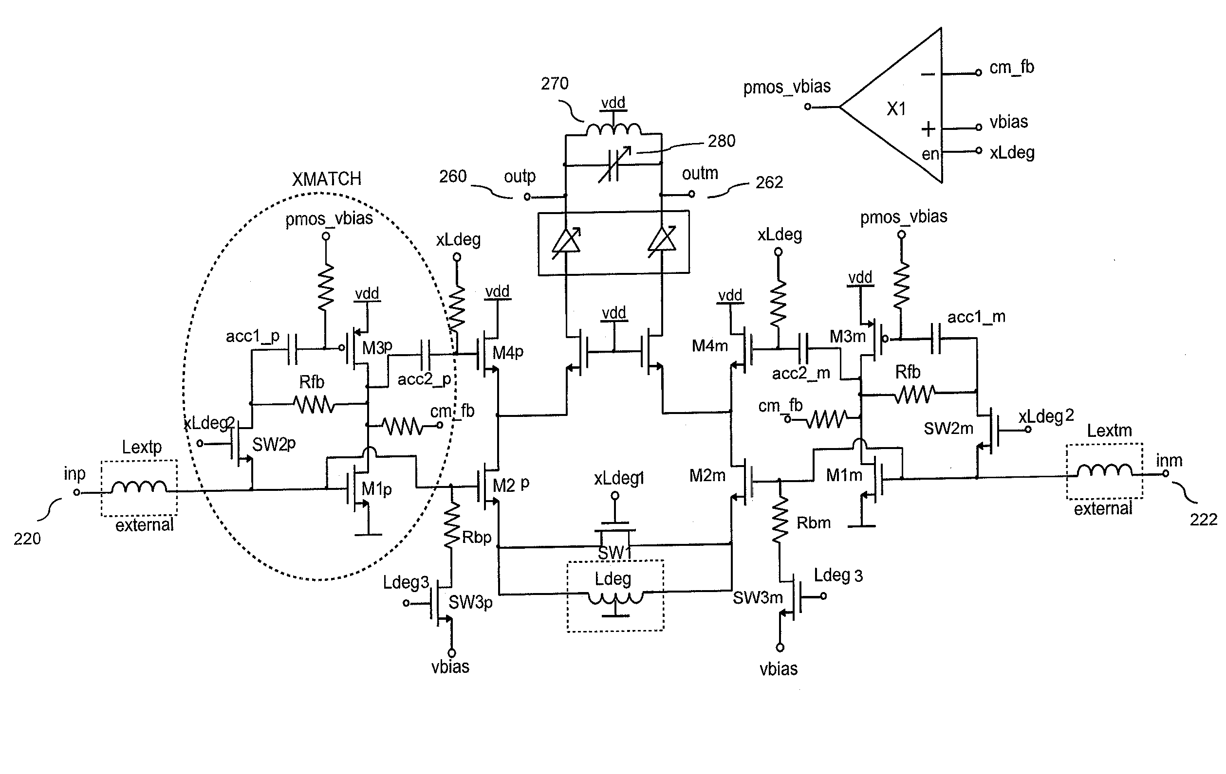
[0009]In accordance with first embodiments, there is a configurable radio-frequency integrated circuit (RFIC) comprising one or more c

Problems solved by technology

Within the user equipment (UE), the size of the antennas is limited due to a small form-factor product thus leading to sub-optimal antenna performance.
Therefore, the platform performance can be degraded at frequencies below 1 GHz leading to decreased uplink / downlink performance.
Due to different uplink / downlink configurations, there are several bands where the RF filter has considerable insertion loss (IL).
As a result, the network design becomes more challenging and more expensive, for example more base stations are needed.
In such cases, additional losses are expected due to diplexer and switch losses, and additional filtering required due to challenging duplex and co-existence scenarios.
Sufficient input matching performance is required because the performance of the RF filter preceding the LNA will degrade if the input of the LNA is not properly matched to a certain input impedance.
Depending on the number of RFIC inputs, the count of the external matching components can become high thus being an expensive and bulky solution.
Since the cost of individual ICs scales down when the number of units increases, it is not economically wise to design separately optimised ICs for different customers and / or products.
From the above it can be seen that there are a number of different design factors to be considered when designing an RFIC, and that accommodating some or all of these factors simultaneously can prove difficult.

Method used


Image

  • Radio Frequency Integrated Circuit
  • Radio Frequency Integrated Circuit
  • Radio Frequency Integrated Circuit

Examples


Embodiment Construction

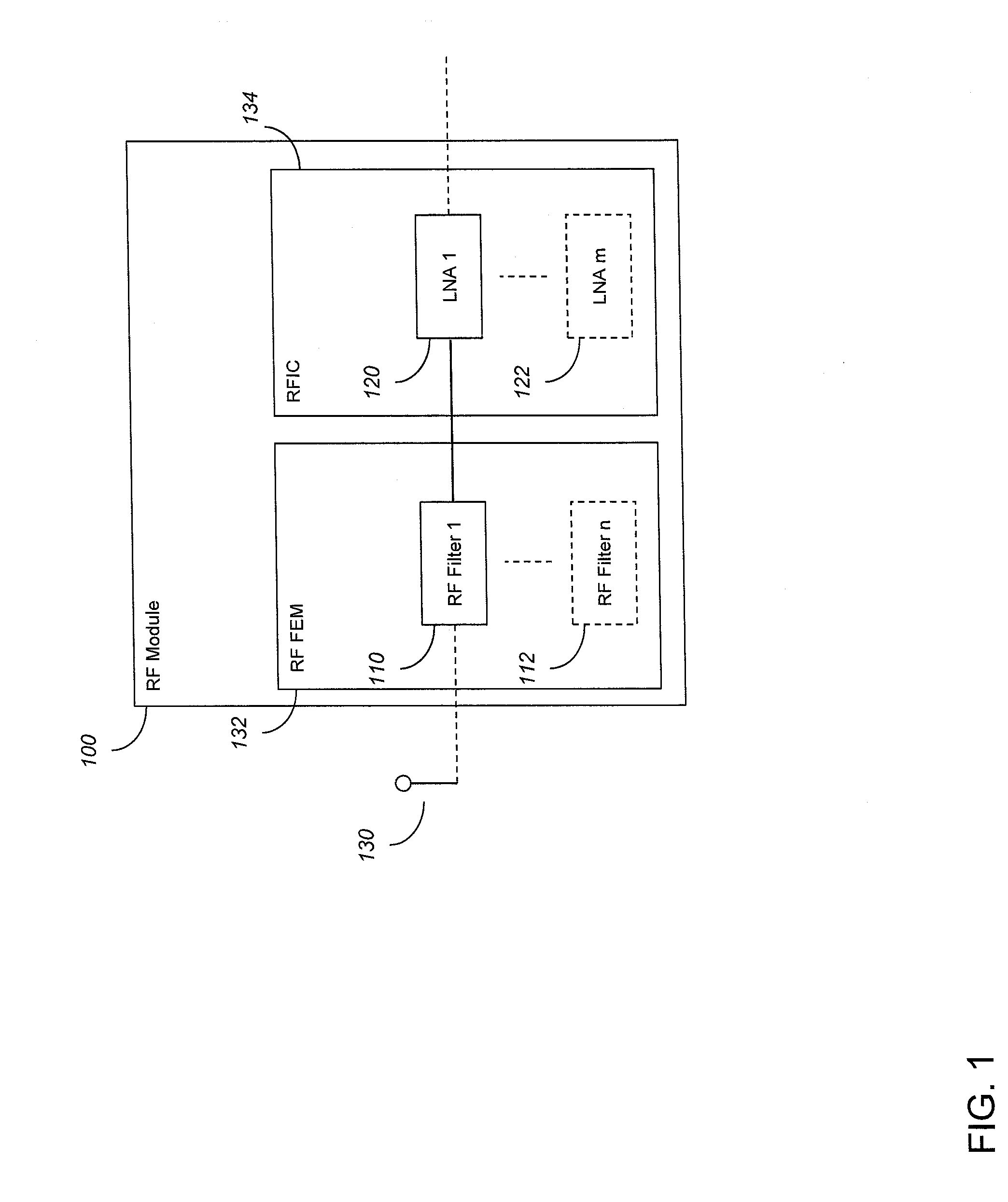
[0040]Receivers typically include one or more radio frequency (RF) filters located between the antenna and the LNA(s) that form the first amplifying stage of the receiver. FIG. 1 illustrates an exemplary receiver comprising an RF module 100 and antenna 130. RF module 100 comprises an RF Front End Module 132 which in turn includes one or more (up to a total of n) RF filters 110-112 that filter radio frequency signals gathered by antenna 130. RF module 100 also comprises an RFIC 134 which in turn comprises one or more (up to a total of m) LNAs 120-122 that amplify the filtered signals generated by the RF filters 110-112.

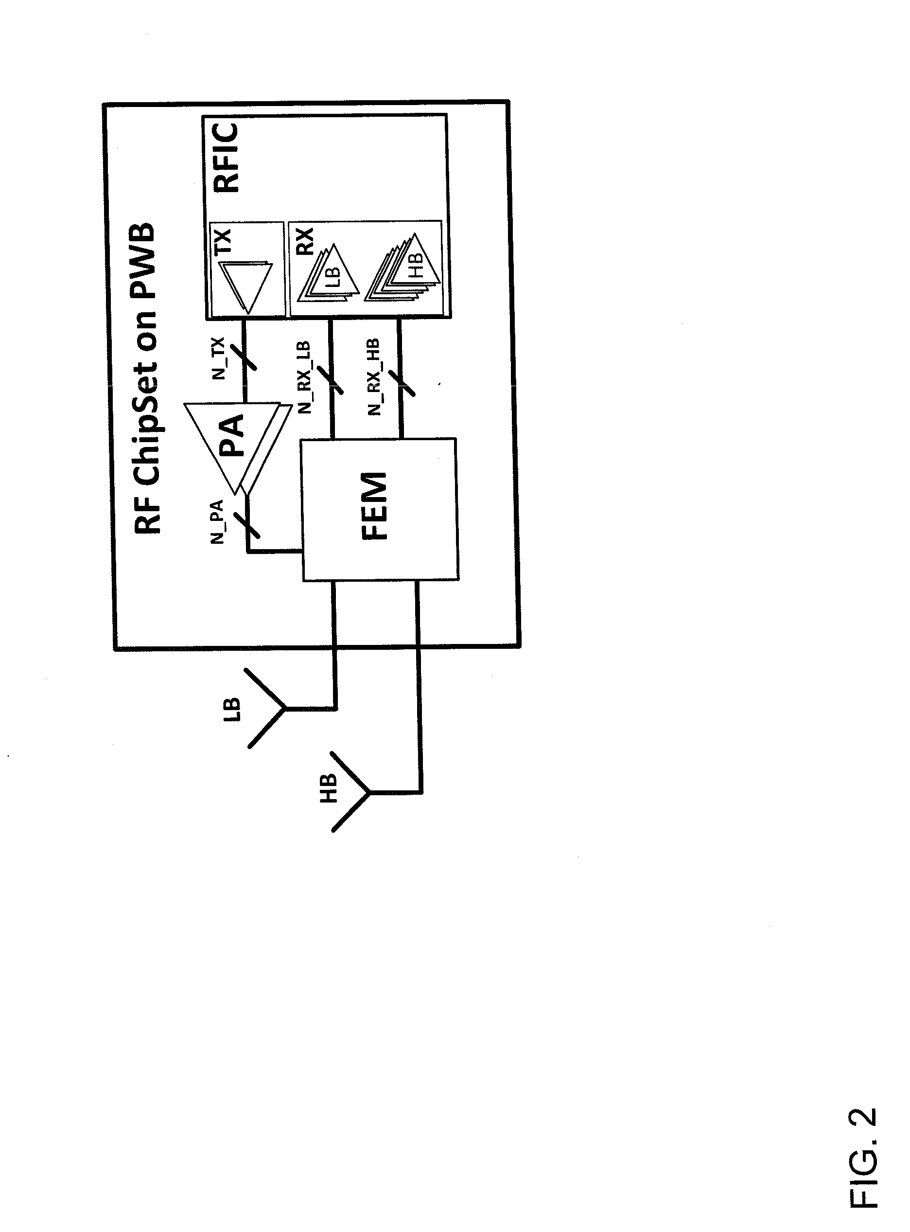
[0041]FIG. 2 illustrates an RF chipset on a PWB for a receiver. The receiver includes a high-band (HB) antenna and a low-band (LB) antenna connected to an RF front end module (FEM). The RF FEM connects to one or more power amplifier modules (PA) and an RFIC. The PA modules may provide more functionality other than amplification functionality. The RFIC comprises a trans...


PUM

PropertyMeasurementUnit
Electric potential / voltageaaaaaaaaaa
Frequencyaaaaaaaaaa
Electric impedanceaaaaaaaaaa

Abstract

Embodiments of the invention are concerned with configurable RFICs. In an exemplary embodiment there is provided a configurable radio-frequency integrated circuit (RFIC) including one or more configurable low noise amplifier circuits, each of said one or more configurable low noise amplifier circuits being configurable between:an internal input impedance matching topology in which the respective low noise amplifier circuit includes one or more internal input impedance matching components adapted to match the input impedance of the respective low noise amplifier to a given input, said one or more internal input impedance matching components being located internally to the respective low noise amplifier circuit; anda topology different from said internal input impedance matching topology.

Description

TECHNICAL FIELD[0001]This application relates to Radio Frequency Integrated Circuits (RFICs). In particular, but not exclusively, this application relates to configurable RFICs.BACKGROUND[0002]Radio-frequency (RF) platforms are high-volume products, which include several integrated circuits (ICs) for audio, power management, radio transceiver, etc. ICs can offer the best economical figures for mass-production products, since the mask costs are fixed which leads to decreasing unit costs as the number of fabricated ICs increases.[0003]The over-the-air (OTA) performance defines the capabilities of the RF platform. OTA performance is an important selling factor and can be a crucial selection criterion for a potential customer, as well as the unit cost. OTA performance is a function of antenna performance and capabilities of RFIC and baseband ICs. Typically, the size of the antenna scales inversely to the RF frequency, i.e. antennas become larger when the wavelength increases. Within the...

Claims


Application Information

Patent Timeline
IPC IPC(8): H03F1/34H05K13/00H03F3/04
CPCH03F1/565H03F3/195H03F3/211H03F3/45179Y10T29/49002H03F2200/294H03F2203/45306H03F2203/45386H03F2203/45704H03F3/45188
Inventor HEIKKINEN, JARI JOHANNESRIEKKI, JONNE JUHANIKAUKOVUORI, JOUNI KRISTIAN
Owner AVAGO TECH INT SALES PTE LTD
Learn More