Printed circuit board production apparatus and printing machine

Active Publication Date: 2012-11-15
YAMAHA MOTOR CO LTD
View PDF3 Cites 0 Cited by
  • Summary
  • Abstract
  • Description
  • Claims
  • Application Information

AI Technical Summary

Benefits of technology

[0009]It is an object of the present invention to provide a printed circuit board production apparatus and a printing machine of the type having a plurality of working units, which are capable of suppressing deterioration in production efficiency during machine setup for any one of the working units, while enhancing the flexibility in working mode.

Problems solved by technology

In this type of conventional component mounting apparatus, as mentioned above, when the working spaces of the two mounting units are not separated from each other, although it becomes possible to enhance the flexibility in working mode, the operations of both of the mounting units are stopped during the machine setup for either one of the mounting units, which causes a problem of deterioration in production efficiency.

Method used


Image

  • Printed circuit board production apparatus and printing machine
  • Printed circuit board production apparatus and printing machine
  • Printed circuit board production apparatus and printing machine

Examples


Embodiment Construction

[0021]The present invention will now be described based on the drawings illustrating an embodiment thereof.

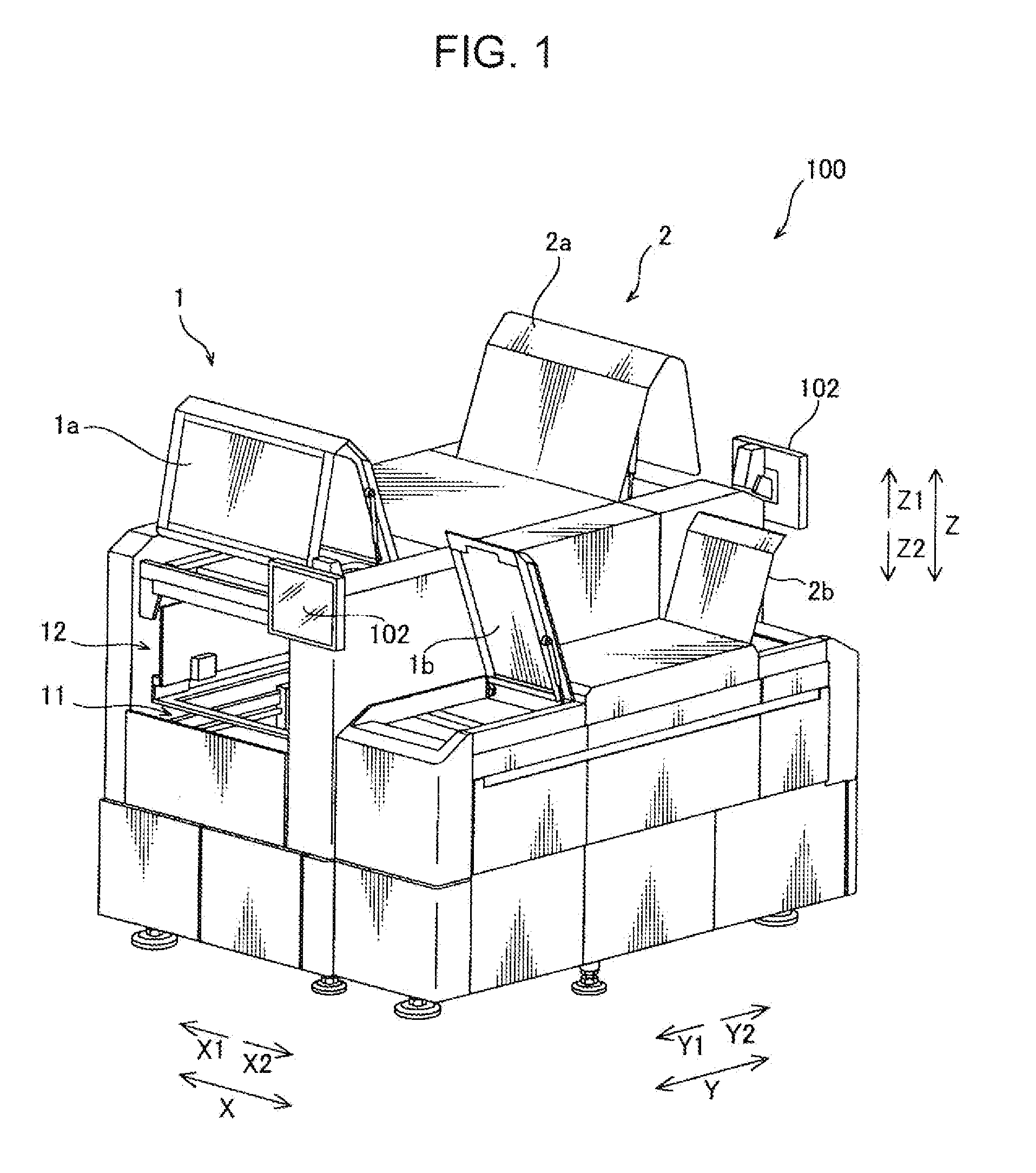
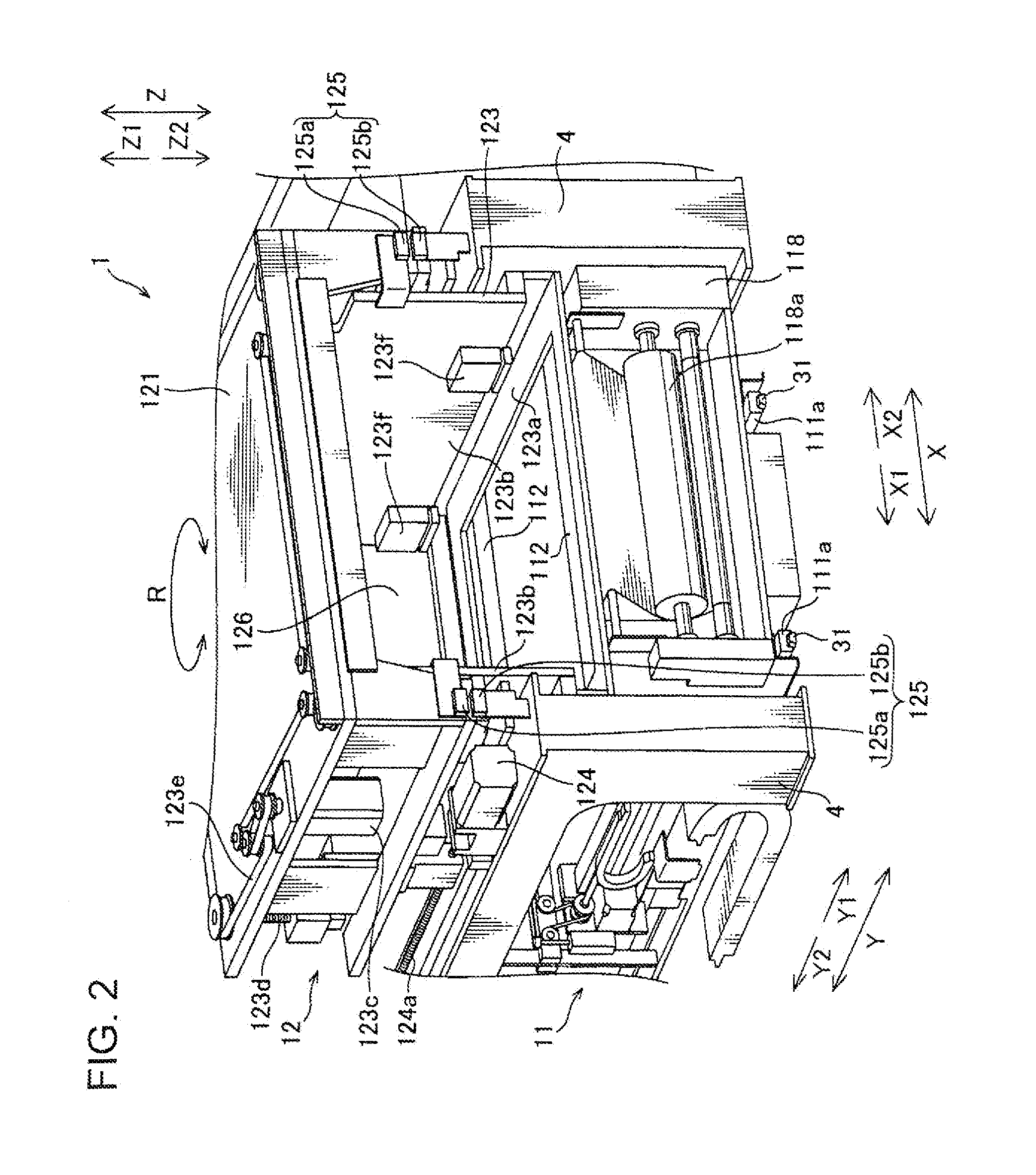
[0022]With reference to FIGS. 1 to 7, a configuration of a printing machine 100 according to one embodiment of the present invention will first be described.

[0023]The printing machine 100 according to this embodiment comprises a first printing unit 1 disposes on one side in a front-back direction (Y direction) (on a side in an Y1 direction), and a second printing unit 2 disposes on the other side (on a side in an Y2 direction). The first printing unit 1 and the second printing unit 2 are disposed adjacent to each other in the front-back direction (Y direction). Each of the first printing unit 1 and the second printing unit 2 has a function of subjecting a board (bare board) to a solder printing process. In this embodiment, each of the first printing unit 1 and the second printing unit 2 serves as one example of a respective one of “first working unit” and “second working unit” ...


PUM


Abstract

Disclosed is a printed circuit board production apparatus which comprises a first working unit, a second working unit, and a control section. The first working unit includes a board conveying section, and a working mechanism section for subjecting the board conveyed to a given working process, wherein the board conveying section and the working mechanism section are configured to be relatively displaceable between a machine-setup position where a gap defined between the board conveying section and the working mechanism section and leading to the second working unit becomes equal to or less than a given value, and a position where the gap becomes greater than the given value. The board conveying section and the working mechanism section are arranged in the machine-setup position by the control section when machine setup for the first working unit is performed during operation of the second working unit.

Description

BACKGROUND OF THE INVENTION[0001]1. Field of the Invention[0002]The present invention relates to a printed circuit board production apparatus and a printing machine, and more particularly to a printed circuit board production apparatus and a printing machine of the type having a plurality of working units.[0003]2. Background Art[0004]Heretofore, as a printed circuit board production apparatus having a plurality of working units, there has been known a component mounting apparatus (printed circuit board production apparatus) having two mounting units (working units), as disclosed, for example, in JP 2010-251450A.[0005]Specifically, a component mounting apparatus disclosed in the JP 2010-251450A comprises: two mounting units each provided with a board conveying path (board conveying section) and a mounting head; and a detachable partition member provided between the two mounting units to separate respective working spaces of the mounting units from each other.[0006]In this component m...

Claims


Application Information

Patent Timeline
IPC IPC(8): B05C13/02
CPCH05K13/0465H05K13/0061B41F15/08B41F15/0818H05K3/0097H05K3/1216
Inventor KOBAYASHI, MOTOKI
Owner YAMAHA MOTOR CO LTD
Why Eureka
Try Eureka