
Photobioreactor comprising rotationally oscillating light sources

a technology of rotating oscillating light source and photobioreactor, which is applied in the direction of bioreactor/fermenter, specific use bioreactor, microorganism, etc., can solve the problems of low productivity of photobioreactor, complex cultivation conditions, or process management, carried out in specially designed photobioreactors,

Inactive Publication Date: 2012-11-08
BAYER INTELLECTUAL PROPERTY GMBH
View PDF0 Cites 25 Cited by
  • Summary
  • Abstract
  • Description
  • Claims
  • Application Information

AI Technical Summary

Problems solved by technology

This, however, entails much more complex requirements for the cultivation conditions, or the process management.
It can only be carried out in specially designed photobioreactors.
However, scale-up and optimal control of this type of photoreactor are difficult so that their productivity is usually low.
With increasing scale, however, the surface area to volume ratio becomes smaller and the light input per unit volume therefore becomes lower, so that the product yield is limited.
The described arrangement of the rods does not, however, allow homogeneous light input into the photobioreactor.
Another disadvantage is that although rotation of the arranged rods is described, this does not involve generating a relative velocity between the light source and the culture liquid comprising the phototrophic organisms.
Patent US 20100028977 A1 furthermore lacks a gasification and degassing concept for the described photobioreactor.
This is another disadvantage since, besides the light input, the supply of carbon dioxide and the discharge of oxygen is also important for algae.
US 20100028977 A1 thus has the disadvantages of light input which is not spatially homogeneous, no relative velocity between the light source and the culture liquid, and a lack of gas transfer concept.
This direct irradiation entails the risk of photoinhibition for particularly sensitive organisms.
Despite enormous interest in recent years, an economically satisfactory solution is not yet available for the cultivation of phototrophic cells, particularly algae and cyanobacteria, in bioreactors.
For shear-sensitive and / or bubble-sensitive organisms, the object described above therefore becomes more difficult.

Method used


Image

  • Photobioreactor comprising rotationally oscillating light sources
  • Photobioreactor comprising rotationally oscillating light sources
  • Photobioreactor comprising rotationally oscillating light sources

Examples


Embodiment Construction

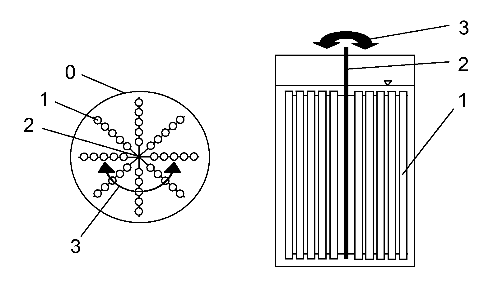
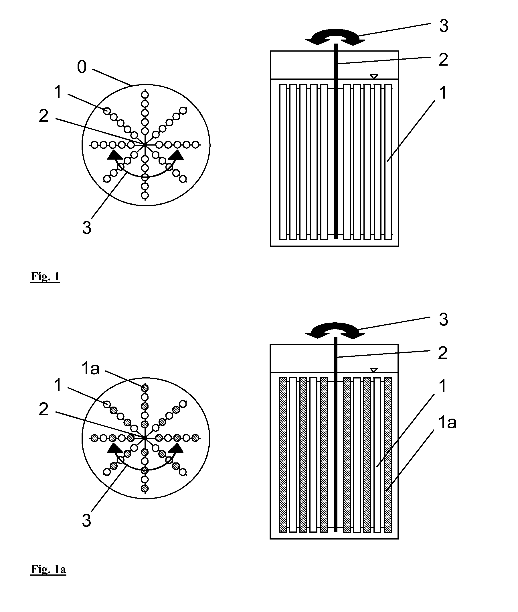
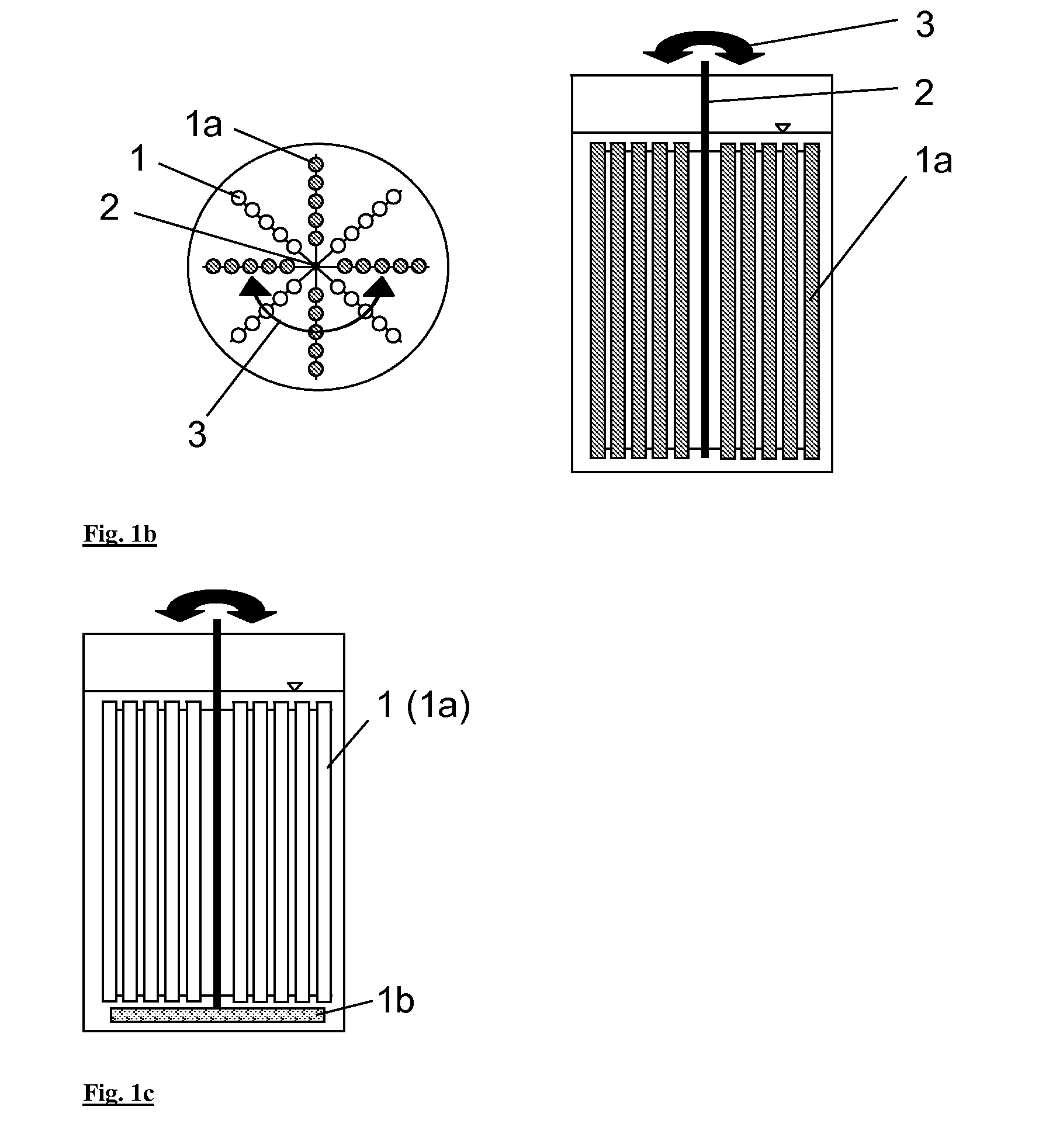
[0029]In this context, the term light source is not necessarily intended to mean that the light source generates the light; rather, the term light source is also used in the sense of light output. For example, the light may be generated outside the photobioreactor and conveyed by glass fibre cable into the bioreactor, where it emerges from light guides. The latter function as a light source for the photobioreactor.

[0030]The invention is suitable not only for phototrophic organisms such as algae and cyanobacteria, but also for other corresponding applications with light input and optionally gasification.

[0031]The light input (preferably in liquids) is used here to provide light for photosynthesis. By applying the light source (for example in a star shape on a rotor), in conjunction with the movement in the liquid, the problem of the short light penetration depth is resolved.

[0032]Usually, the light sources are fixed on one or more carriers. Suitable carriers are membrane surfaces suc...


PUM

PropertyMeasurementUnit
frequencyaaaaaaaaaa
volumeaaaaaaaaaa
movementaaaaaaaaaa

Abstract

The invention relates to a photobioreactor having illumination by light sources (light guides, LEDs) moved in rotational oscillation, and optionally membrane surfaces for gas transport moved in combination in rotational oscillation.Advantages are, inter alia, light input which is spatially homogeneous on average over time and can be adapted by means of intensity and oscillation to the culture and its density, as well as low-shear power input and optionally low-shear bubble free gasification and degassing.

Description

CROSS REFERENCE TO RELATED APPLICATION[0001]This application claims the priority to German Application No. 102011075110.6, filed May 3, 2011, the content of which is incorporated herein by reference in its entirety.BACKGROUND[0002]1. Field of the Invention[0003]The present invention relates to a photobioreactor which comprises light sources mobile in rotational oscillation inside the reactor for spatially homogeneous light input.[0004]2. Description of Related Art[0005]The invention may be used for the cultivation of phototrophic organisms, which are irradiated in an optimized fashion by the light sources mobile in rotational oscillation inside the reactor.[0006]This optimized light input may optionally be combined with optimized gasification and degassing for shear-sensitive reactor content substances such as shear-sensitive phototrophic organisms.[0007]One important field of application of phototrophic organisms is the cultivation of algae. Besides the traditional cultivation of a...

Claims


Application Information

Patent Timeline
Patent Type & Authority Applications(United States)
IPC IPC(8): C12M1/42C12N1/12
CPCC12M21/02C12M31/12C12M29/04
Inventor BROD, HELMUTFRAHM, BJOERN
Owner BAYER INTELLECTUAL PROPERTY GMBH
Learn More