
Gantry comprising beam analyser for use in particle therapy

a particle therapy and beam analysis technology, applied in the field of rotating gantry, can solve the problems of large building footprint, increase in beam emittance and energy spread, and not all accelerator types can vary the energy, so as to reduce the cost and size of the particle therapy facility

Active Publication Date: 2012-11-08
ION BEAM APPL
View PDF7 Cites 47 Cited by
  • Summary
  • Abstract
  • Description
  • Claims
  • Application Information

AI Technical Summary

Benefits of technology

[0016]The additional function of limiting the energy spread of the entering particle beam to a selected maximum value.With the present invention, the ESS functionality of limiting the energy spread or momentum spread of the beam to a selected value is performed by the gantry system itself. Hence the size and cost of a particle therapy facility can be reduced.In the context of the present invention, the momentum spread is defined as the standard deviation of the momentums of the particles at a given location and is expressed as a percentage of the average momentum of all particles at this location. Whatever the location of the means for limiting the momentum spread in the gantry, these means are preferably designed for limiting said momentum spread to 10%, more preferably to 5%, and even more preferably to 1% of the average momentum of all particles.
[0018]More preferably, the gantry according to the invention also comprises a collimator installed in-between the gantry entrance point and a first quadrupole magnet in the gantry. This collimator is used for reducing the emittance of the beam before the beam is arriving at the first magnet in the gantry beam line.

Problems solved by technology

However, not all accelerator types can vary the energy.
As a result of this energy degradation, there is an increase in emittance and energy spread of the beam.
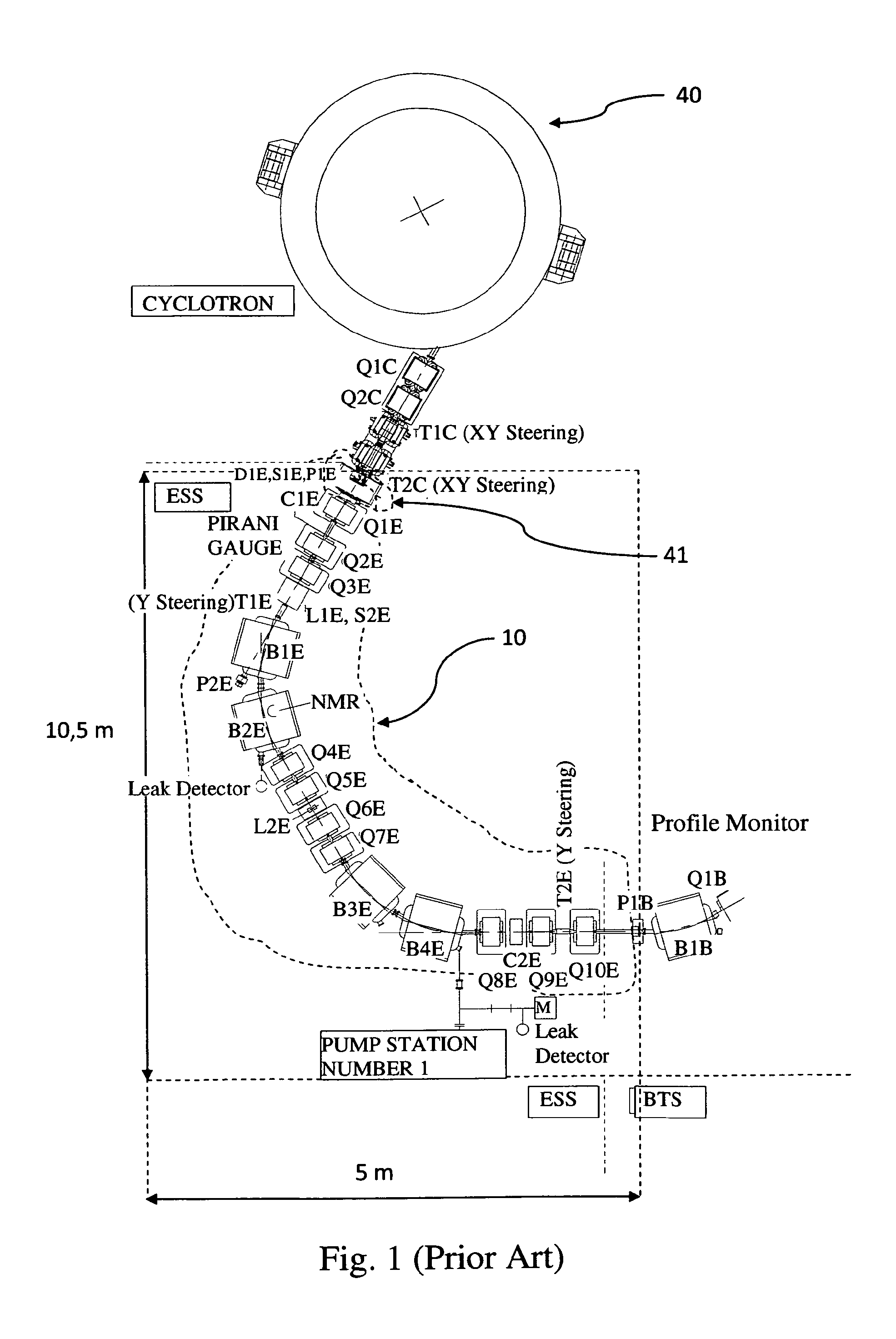
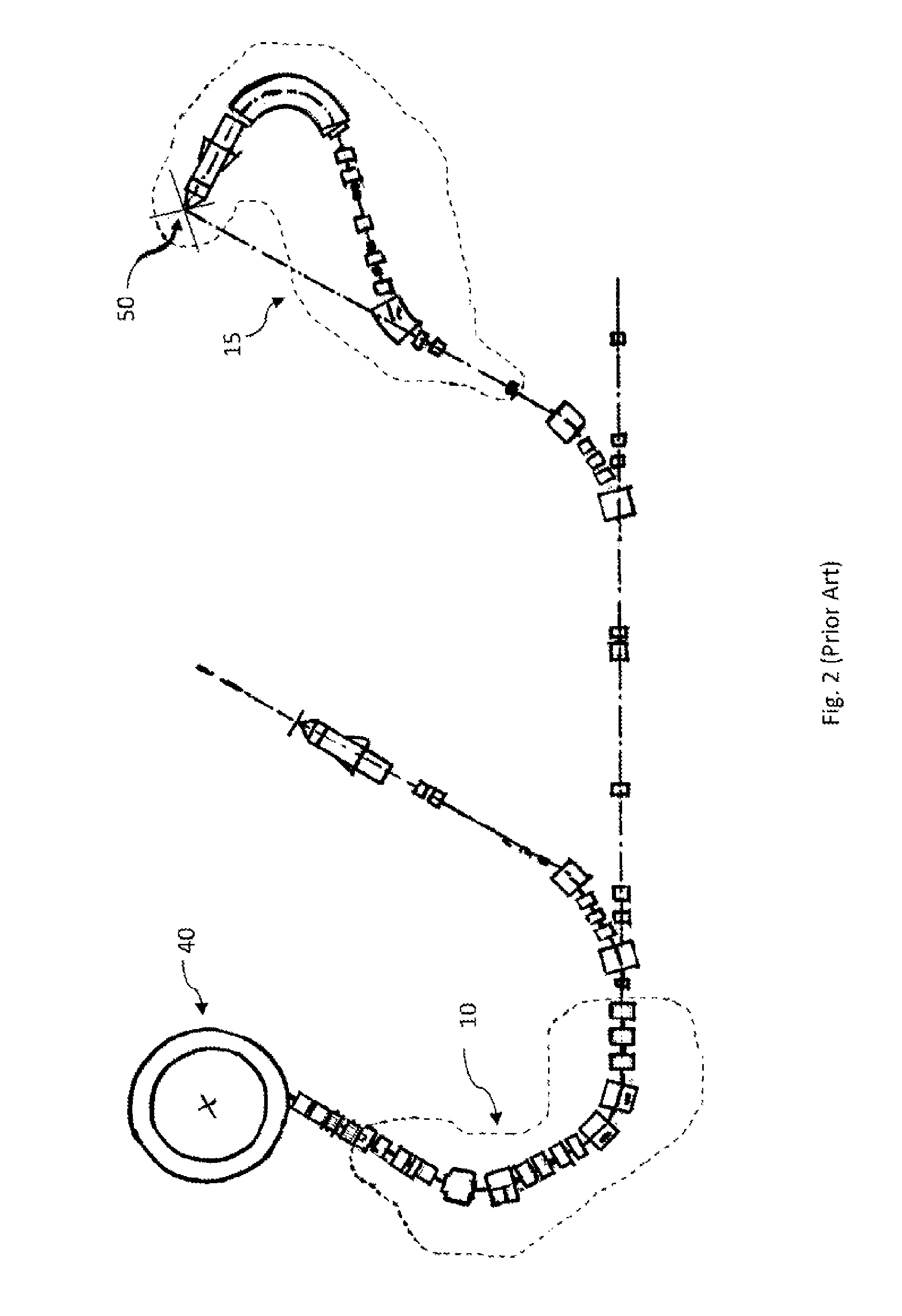
A disadvantage of the use of such a degrader and energy analyser is that this device requires a relative large space area as shown in FIG. 1 and hence a large building footprint is required.
The installation of an ESS results also in an extra equipment cost.

Method used


Image

  • Gantry comprising beam analyser for use in particle therapy
  • Gantry comprising beam analyser for use in particle therapy
  • Gantry comprising beam analyser for use in particle therapy

Examples


Embodiment Construction

[0029]The present invention will now be described in detail in relation to the appended drawings. However, it is evident that a person skilled in the art may conceive several equivalent embodiments or other ways of executing the present invention. The drawings described are only schematic and are non-limiting. In the drawings, the size of some of the elements may be exaggerated and not drawn on scale for illustrative purposes.

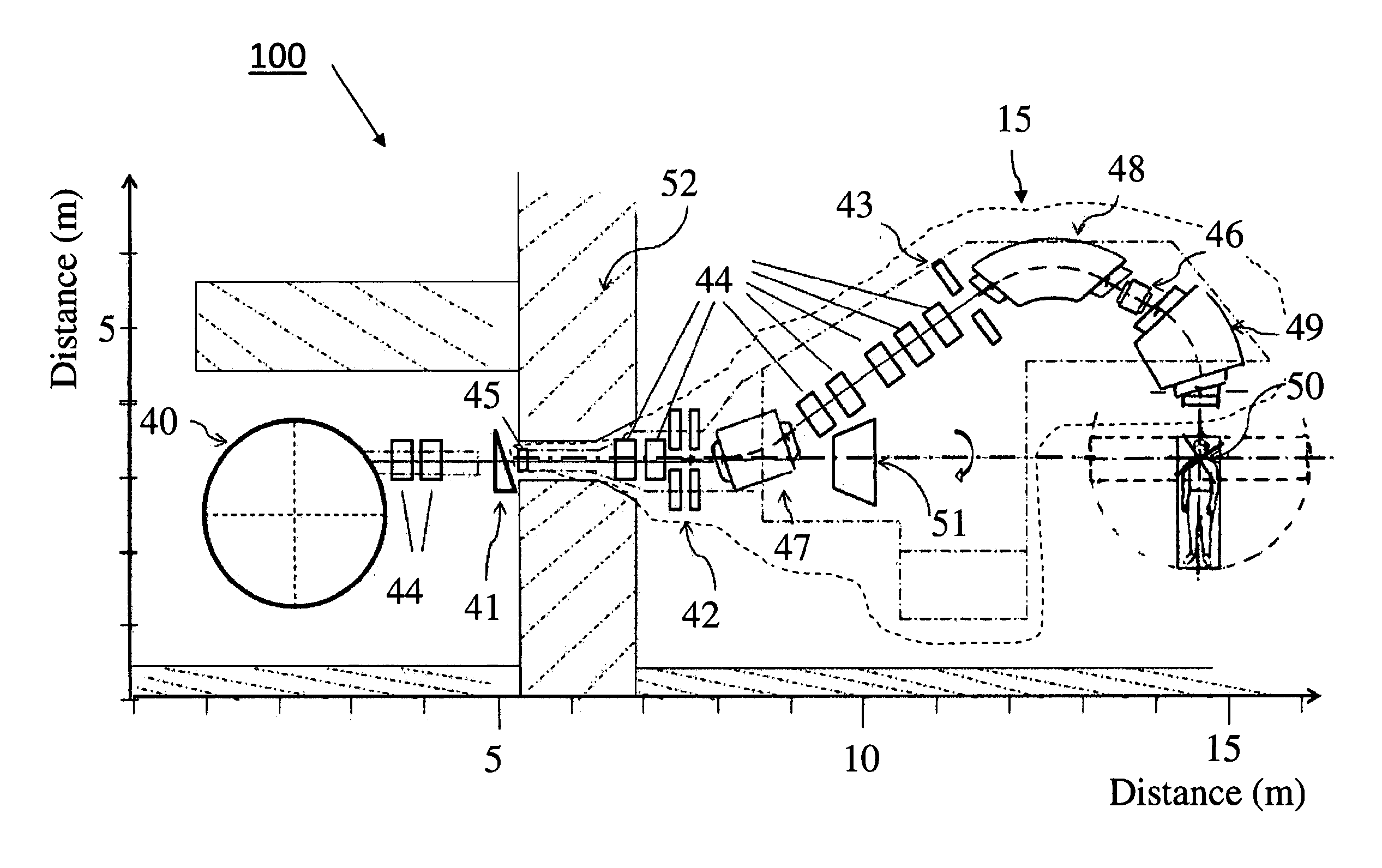
[0030]A exemplary particle therapy configuration according to the invention is shown in FIG. 4. In this example, the rotatable gantry according to the invention is coupled with a stationary-, fixed energy-particle accelerator 40 to form a single room particle therapy apparatus 100. An example of a particle accelerator for protons is a superconducting synchrocyclotron which has a compact geometry (e.g. with an extraction radius of 1.2 m). The gantry according to the invention is installed in the gantry room and a shielding wall (e.g. a 1.7 m thick concrete wall)...


PUM


Abstract

The present invention relates to a particle therapy apparatus used for radiation therapy. More particularly, this invention relates to a gantry for delivering particle beams which comprises means to analyse the incoming beam. Means are integrated into the gantry to limit the momentum spread of the beam and / or the emittance of the beam.

Description

FIELD OF THE INVENTION[0001]The present invention relates to a charged particle therapy apparatus used for radiation therapy. More particularly, this invention relates to a rotatable gantry designed for receiving a charged particle beam in a direction substantially along a rotation axis of the gantry, for transporting and for delivering said beam to a target to be treated.STATE OF THE ART[0002]Radiotherapy using charged particles (e.g. protons, carbon ions, . . . ) has proven to be a precise and conformal radiation therapy technique where a high dose to a target volume can be delivered while minimizing the dose to surrounding healthy tissues. In general, a particle therapy apparatus comprises an accelerator producing energetic charged particles, a beam transport system for guiding the particle beam to one or more treatment rooms and, for each treatment room, a particle beam delivery system. One can distinguish between two types of beam delivery systems, fixed beam delivery systems d...

Claims


Application Information

Patent Timeline
IPC IPC(8): A61N5/10
CPCA61N5/10A61N5/1081G21K5/04G21K1/093A61N2005/1087A61N5/01A61N5/103G21K1/02
Inventor JONGEN, YVES
Owner ION BEAM APPL
Learn More