Vapor barrier ceiling seal apparatus

a technology of vapor barrier and ceiling seal, which is applied in the direction of electrical apparatus, spatial arrangement/disposition of cables, constructions, etc., can solve the problems of ineffectiveness and time-consuming, and achieve the effects of reducing volume, preventing enclosure collapse, and increasing cavity volum

Inactive Publication Date: 2012-11-08
BRAINWAVE RES CORP
View PDF3 Cites 3 Cited by
  • Summary
  • Abstract
  • Description
  • Claims
  • Application Information

AI Technical Summary

Benefits of technology

[0010]The flexible enclosure may be collapsible for insertion through an opening in a pre-existing ceiling substrate or for use in new building construction. The enclosure sides can be compressed to provide a reduced volume for the cavity prior to installation and expanded to increase the cavity volume during installation. For example, the enclosure wall can be bellows-shaped and expanded to fit the clearance between ceiling joists. A support structure, for example, a helical spring can be inserted into the enclosure in its expanded state to prevent collapse of the enclosure from the weight of insulation or the like.

Problems solved by technology

Such efforts become time intensive and ineffective as they are susceptible to breakage.

Method used


Image

  • Vapor barrier ceiling seal apparatus
  • Vapor barrier ceiling seal apparatus
  • Vapor barrier ceiling seal apparatus

Examples


Embodiment Construction

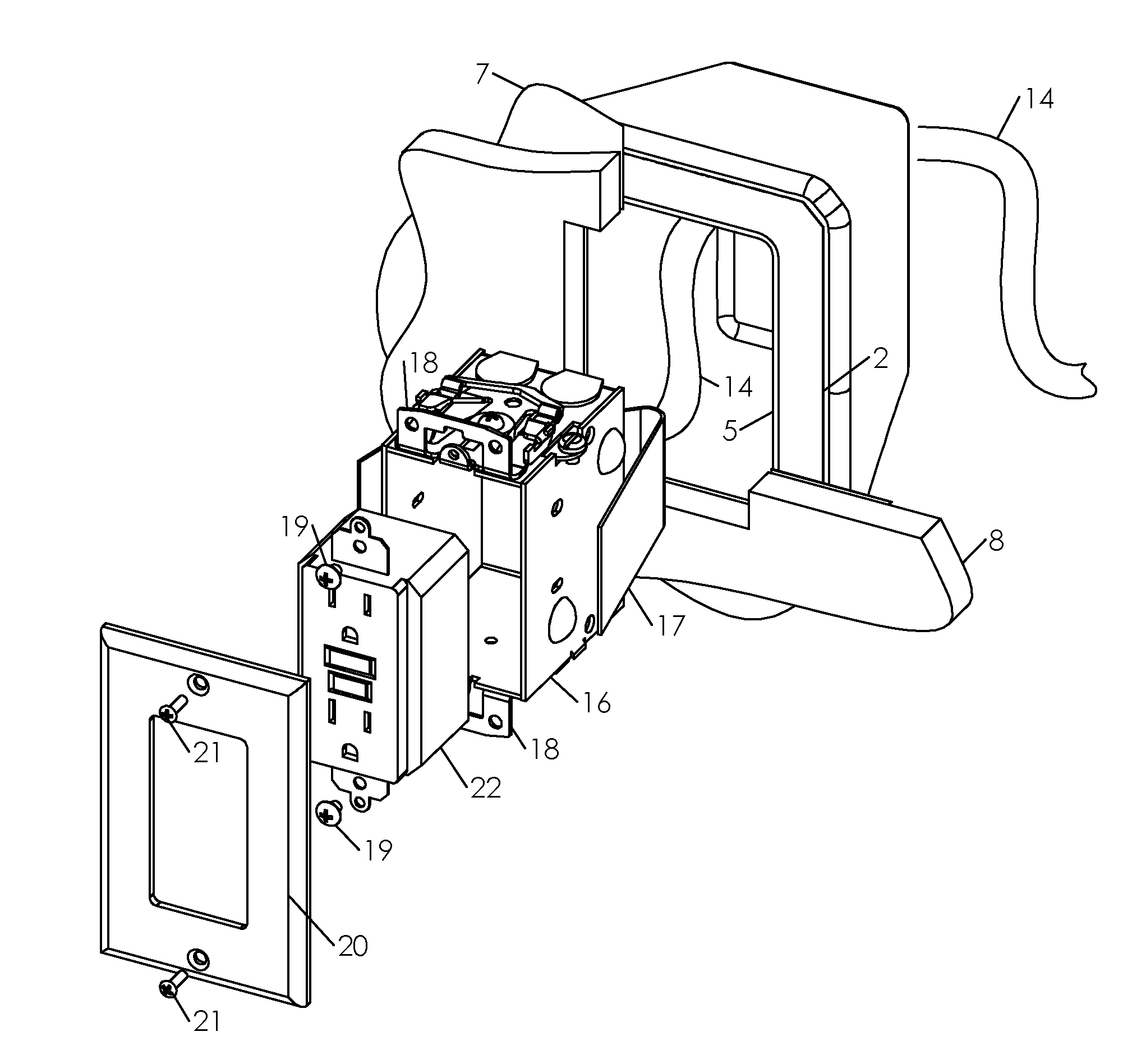
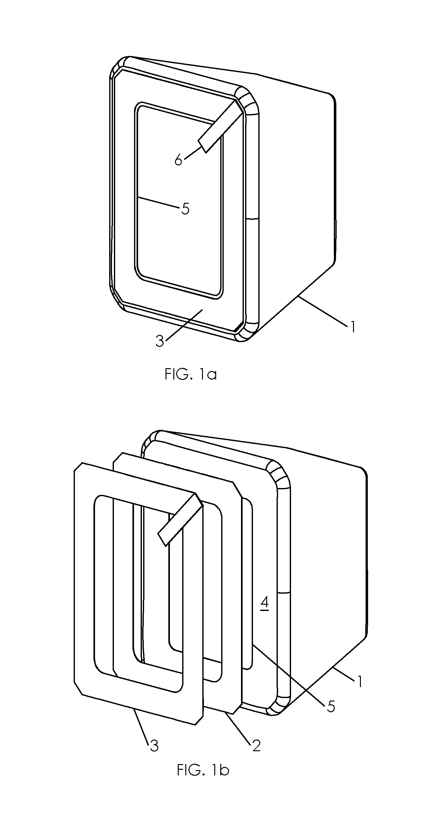
[0092]As shown in the perspective view of FIG. 1a and the exploded view of FIG. 1b, enclosure 1 can be used to seal a hole in an air / vapor barrier membrane situated behind drywall 8 in a building. Enclosure 1 can be made of a flexible material, such as 0.006 thick polyethylene or the like, by blow molding. Adhesive 2 and release paper 3 are applied to the planar surface 4 around the aperture 5. Pull tab 6 allows the release liner to be withdrawn after the enclosure is in place.

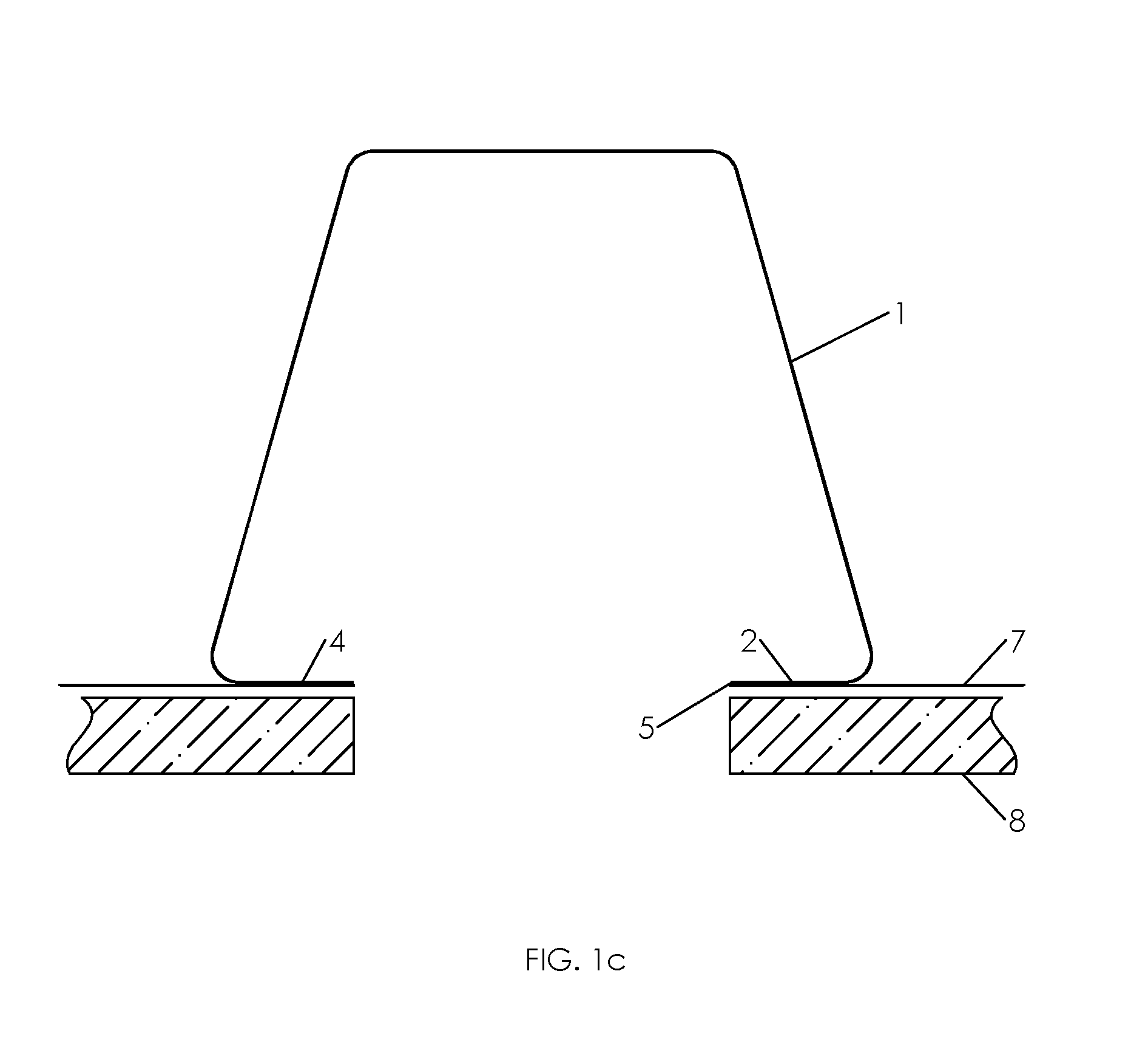
[0093]FIG. 1c shows the enclosure 1 in section view, positioned behind drywall 8. A planar member having a surface 4 of the enclosure is bonded with adhesive 2 to the inner side of the barrier membrane 7 that surrounds an opening in the membrane. The planar member provides an undercut to facilitate manual access to the inside of the planar member. In installation, a finger, hand or tool can be inserted into the enclosure 1 to apply pressure to the opposite side of planar surface 4 to compress the adhesive 2 an...


PUM


Abstract

An opening in a vapor barrier membrane interior to a ceiling can be sealed by a flexible enclosure. A planar member of the enclosure can be bonded to the inner side of the membrane. The enclosure is formed with a cavity that can encompass a ceiling mounted electrical device. A fastener is joined to the planar member permits bonding thereof with an interior surface of the membrane by manual application of a compressive force. The fastener may comprise a removable release liner covering an adhesive.

Description

[0001]This is a continuation-in-part of application Ser. No. 13 / 185,144, filed Jul. 18, 2011 on behalf of inventors Guy Gagne and James Rogers, claiming the benefit of provisional application 61 / 483,254 under 35 U.S.C. 119(e).BACKGROUND[0002]This disclosure is related to preservation of vapor barriers in building structures. More particularly, integrity of vapor barrier functionality is maintained when access to the interior of a wall or ceiling requires breaching a vapor barrier membrane.[0003]Vapor barriers are required to prevent condensation that would otherwise occur from interaction between cold ambient air from outside the building and the warmer inside air. A vapor barrier seals against cold air flow within wall and ceiling spaces. In various situations, it would be desirable to gain access within an existing wall or ceiling that has been protected by a vapor barrier. For example, addition of accessories such as electrical boxes, data ports, light fixtures, speakers or the l...

Claims


Application Information

Patent Timeline
Patent Type & Authority Applications(United States)
IPC IPC(8): H02G7/05H02G3/22
CPCH02G3/20
Inventor GAGNE, JEAN-GUYROGERS, JAMES W.
Owner BRAINWAVE RES CORP
Why Eureka
Try Eureka