
Living donor cannula

a cannula and donor technology, applied in the field of cannulas and clamping methods, can solve the problems of not being suitable for use with organs, and achieve the effect of less tissue and easy viewing

Active Publication Date: 2012-11-01
LIFELINE SCI
View PDF2 Cites 10 Cited by
  • Summary
  • Abstract
  • Description
  • Claims
  • Application Information

AI Technical Summary

Benefits of technology

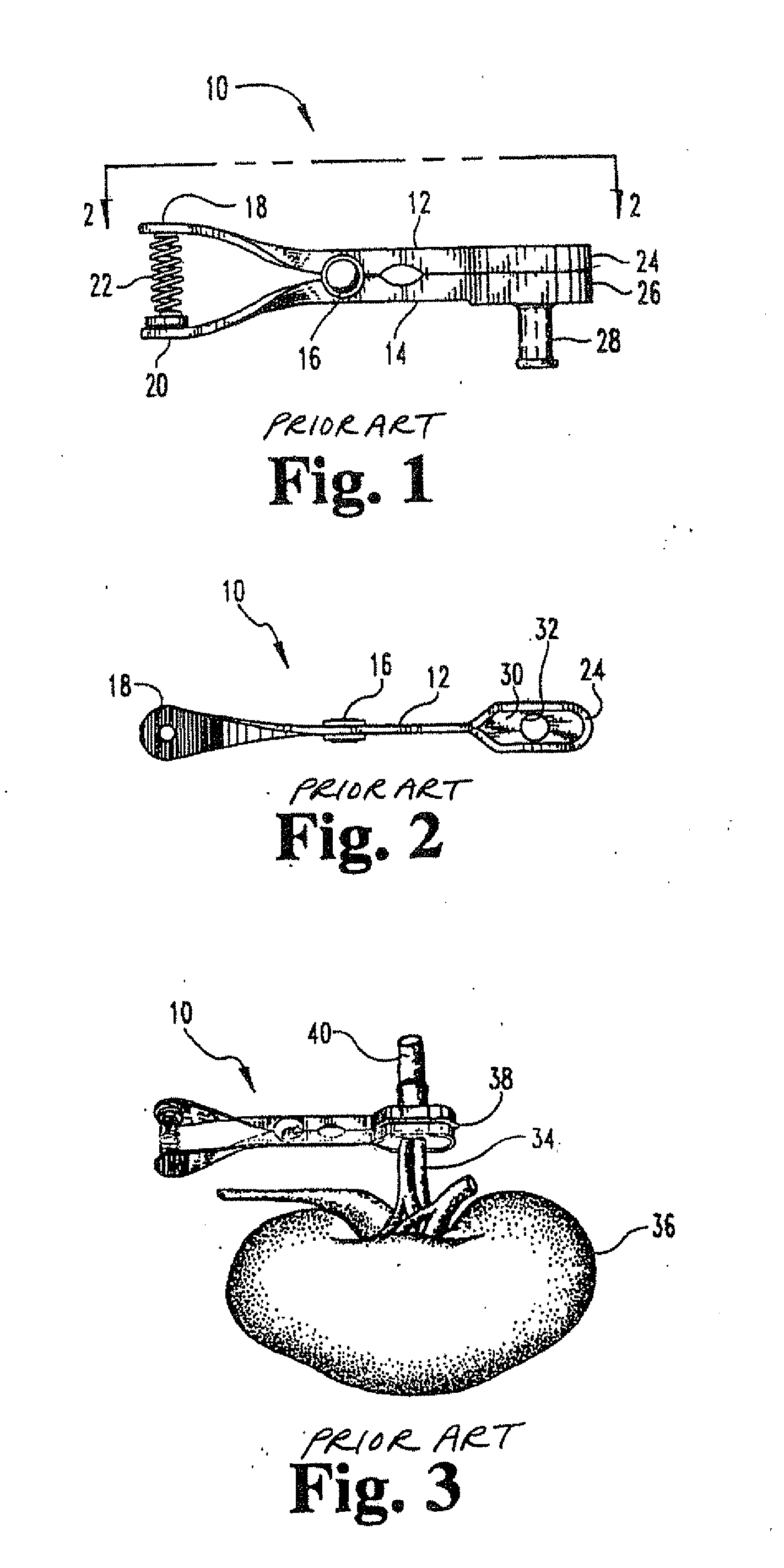
[0008]The cannulas as described above require the use of an aortic patch also known as a Carrel patch, or cuff. An aortic patch is a section of the aorta that remains attached to the organ when the organ is removed from an organ donor. The aortic patch is used to facilitate cannulation of vasculature of the donated organ. An aortic patch is typically only available from a deceased donor because of the resultant damage to the aorta required for an aortic patch. As such, the cannulas described above suffer from a problem in that they are not suitable for use with organs, such as a kidney, donated from a living donor or organs where an aortic patch is otherwise not available. With such an organ, the amount of tissue available for cannulation is much less. Care must be taken not to damage the limited amount of tissue available when attaching a cannula so that adequate tissue remains to reconnect the organ when the organ is transplanted to the recipient, and to prevent damage that could result in loss of the organ.
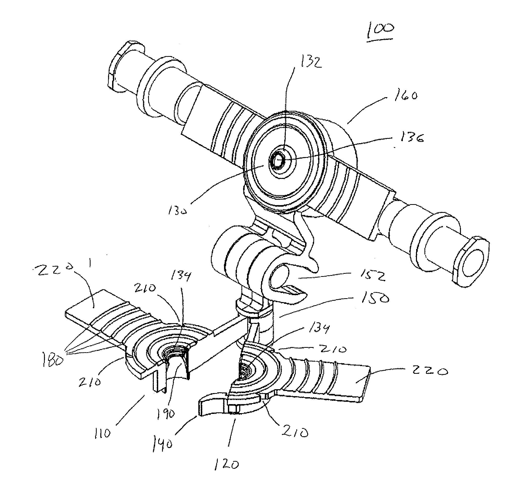
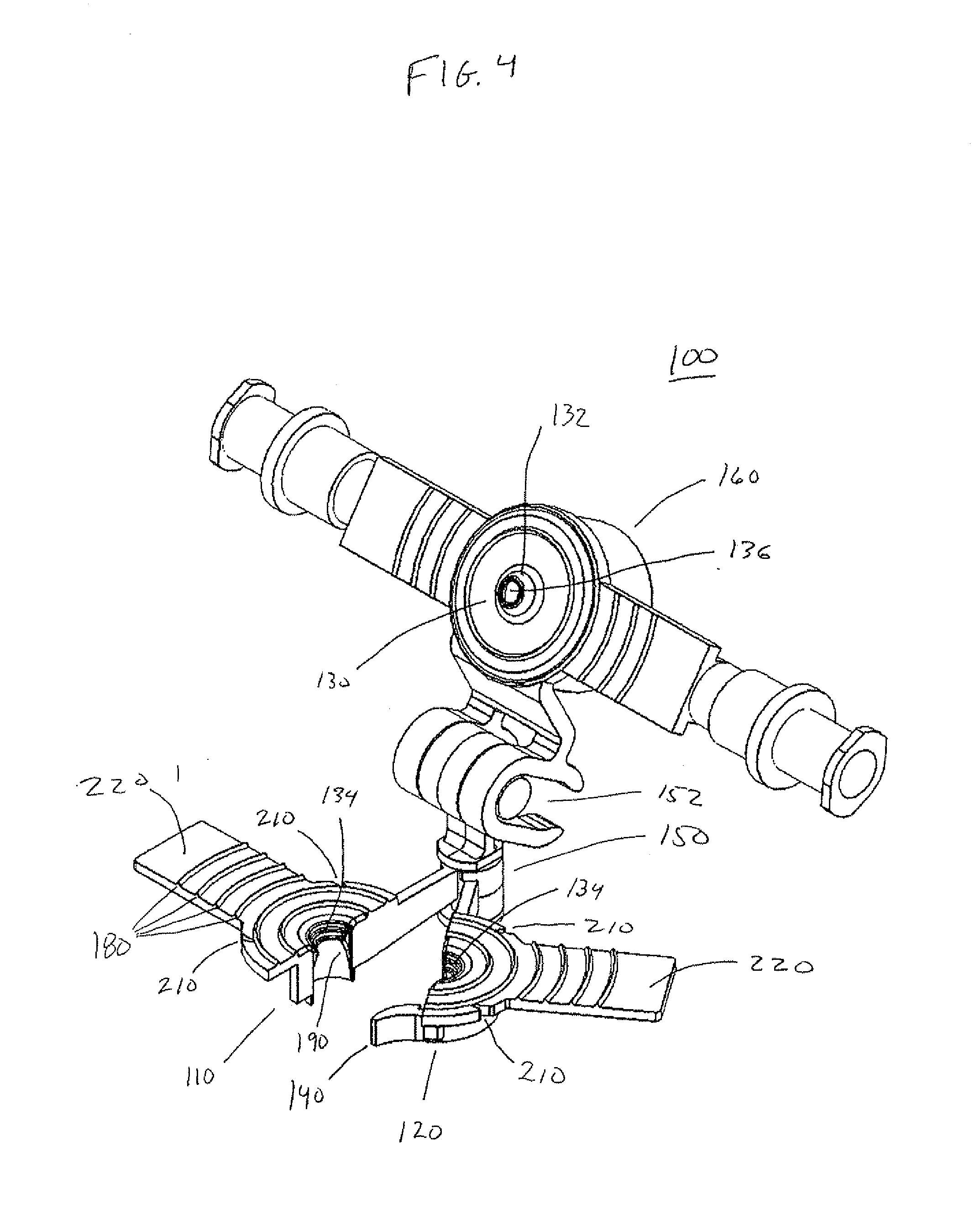
[0011]Exemplary implementations of the broad inventive principles described herein provide a cannula with an optically clear portion configured to allow a user to view at least one portion of an interior of vasculature and a seal when the cannula is in a position in which an end of the vasculature is secured by the cannula. The optically clear portion provides optical magnification of the artery in relation to its position in the cannula. These exemplary implementations provide a solution to problems and disadvantages discussed above because they allow for inspection of the vasculature for damage and proper connection while cannulated. The magnification may also allow the clinician to observe for trapped air bubbles or clots, or to observe the intima of the artery for damage. Also, these exemplary implementations require less tissue from the vasculature to be used because the tissue can be readily viewed in the cannula to confirm that the cannula is properly connected. Thus, excess tissue does not need to be used in order to confirm that the tissue is properly cannulated.

Problems solved by technology

An aortic patch is typically only available from a deceased donor because of the resultant damage to the aorta required for an aortic patch.
As such, the cannulas described above suffer from a problem in that they are not suitable for use with organs, such as a kidney, donated from a living donor or organs where an aortic patch is otherwise not available.

Method used


Image

  • Living donor cannula
  • Living donor cannula
  • Living donor cannula

Examples


Embodiment Construction

[0017]Preservation of organs by machine perfusion has been accomplished at hypothermic temperatures with or without computer control with crystalloid perfusates and without oxygenation. See, for example, U.S. Pat. Nos. 5,149,321, 5,395,314, 5,584,804, 5,709,654 and 5,752,929 and U.S. patent application Ser. No. 08 / 484,601 to Klatz et al., which are hereby incorporated by reference.

[0018]Ideally organs would be procured in a manner that limits their warm ischemia time to essentially zero. Unfortunately, in reality, many organs, especially from non-beating heart donors, are procured after extended warm ischemia time periods (i.e. 45 minutes or more). The machine perfusion of these organs at low temperature has demonstrated significant improvement (Transpl Int 1996 Daemen). Numerous control circuits and pumping configurations have been utilized to achieve this objective and to machine perfuse organs in general. See, for example, U.S. Pat. Nos. 5,338,662 and 5,494,822 to Sadri; U.S. Pat...


PUM


Abstract

Disclosed is a cannula including a first circumferential portion, a second circumferential portion, and a seal with a first clamping surface. The first circumferential portion and the second circumferential portion are configured to mutually cooperate to support a circumference of vasculature, and form a second clamping surface. The first clamping surface and the second clamping surface are configured to cooperate to secure an end of the vasculature.

Description

BACKGROUND[0001]I. Related Technical Fields[0002]Related technical fields include cannulas and clamping methods, and more specifically, cannulas and clamping methods for perfusing one or more organs to monitor, treat, sustain and / or restore the viability of the organ(s) and / or for transporting and / or storing the organ(s).[0003]II. Related Art[0004]Various devices have been developed that couple the anatomy of an organ being perfused to a machine or other equipment. Such devices are typically referred to as perfusion clamps or simply cannulas. Although the term cannula in general use has other meanings, the term cannula is used generically throughout the specification to refer to a clamp or other device that provides a connection through which a fluid flow may be established.[0005]A type of cannula as described in U.S. Pat. No. 5,728,115 to Westcott et al., which is hereby incorporated by reference, is shown in FIGS. 1-3. A clamping device (cannula) 10 is used to couple the perfusion...

Claims


Application Information

Patent Timeline
IPC IPC(8): A61M5/00
CPCA61M39/0247A61M1/1008A61M39/284A61M39/28
Inventor KRAVITZ, DAVIDSTEINMAN, CHRISTOPHERPETTINATO, DAVID
Owner LIFELINE SCI
Learn More