
Method for critical path scheduling of activity time segments

a critical path and activity time segment technology, applied in the field of computerized scheduling methods, can solve the problems of introducing errors in float calculations, complicating the scheduling process, and cpm-based scheduling remains a challenging process, and achieve the effect of meeting time, cost and resource constraints

Inactive Publication Date: 2012-10-18
HEGAZI TAREK MOHAMED MOHAMED
View PDF8 Cites 8 Cited by
  • Summary
  • Abstract
  • Description
  • Claims
  • Application Information

AI Technical Summary

Benefits of technology

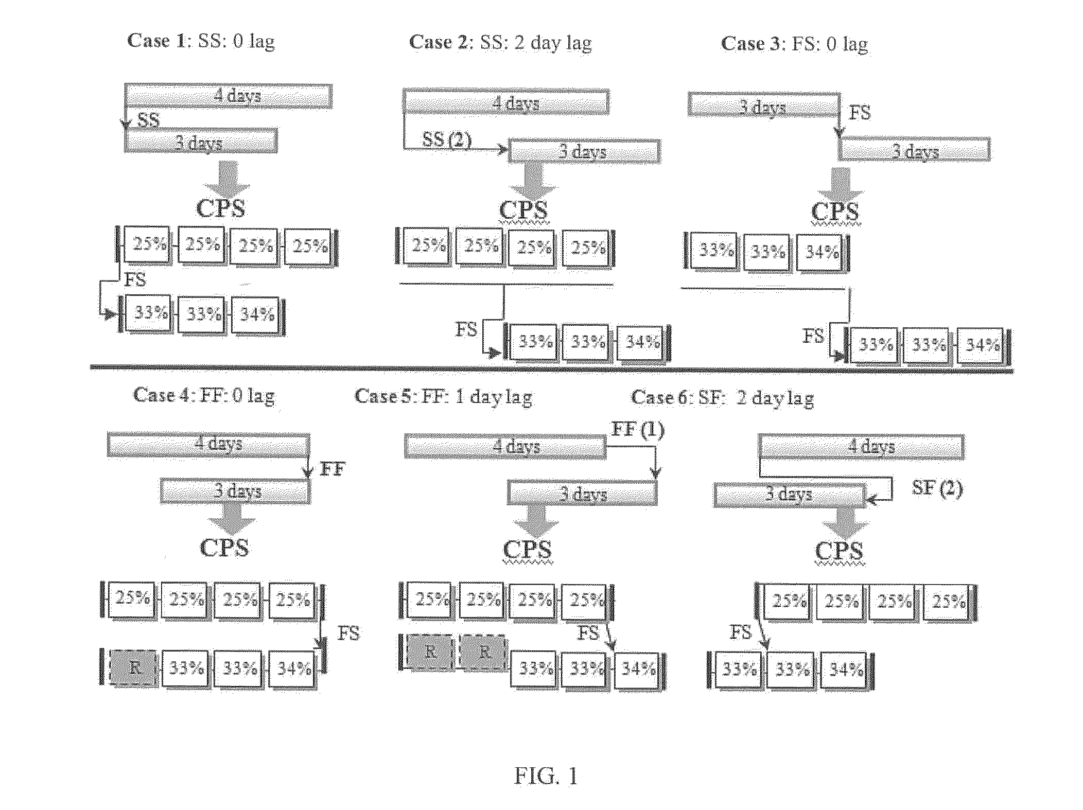
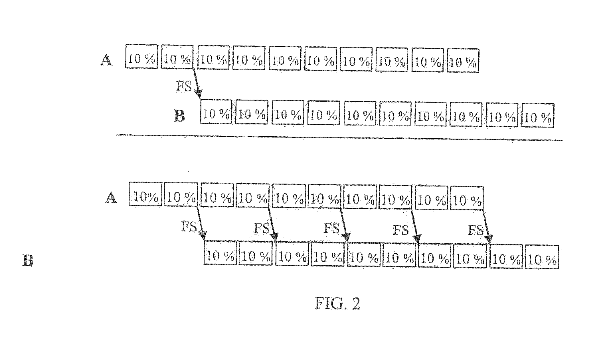
[0008]The present invention introduces a novel method of project management, which introduces a scheduling method coined herein as “Critical Path Segments” (CPS), in which activity duration is not a continuous block of time, rather a group of segmented time segments attached to each other. The method of the present invention can be adapted to include innovative scheduling features such as automatic conversion of all project relations to finish-to-start, time and cost optimization, audio / visual progress recording, delay analysis, rework analysis, and visualization features. These features can help meet the time, cost, and resource constraints of single, multiple, and repetitive projects. The method of the present invention can further be adapted to provide effortless documentation of all progress events, location-based GIS features to help manage multiple projects, and can be adapted to produce extensive visual reports shown directly on 2D / 3D project drawings.

Problems solved by technology

While the CPM calculations are simple and straightforward, CPM-based scheduling remains a challenging process.
At the planning stage, the CPM network may contain complex relationships that complicate the scheduling process and introduce errors in float calculations.
This difficulty adds to the perception that CPM and existing CPM systems are useful for organizational and reporting purposes, but not for decision support to reflect and react to reality.
While the schedule acts as a baseline for measuring progress, it is difficult to use it to initiate appropriate corrective actions for recovering delays and overruns.
CPM schedules, however, are difficult to analyze due to many well-documented factors that impact calculation accuracy and repeatability, including but not limited to problems with multiple complex relationships among project tasks; networks with multiple relations (FF and SS) are complex to analyze and cause parts of an activity, not the whole, to be critical, which are not readily detectable; non-finish-to-start relationships with lags complicate total float determination and interpretation, potentially affecting critical path identification; SS and FF relationships use time, but not work-amount, lags; inaccurate schedule calculations; floats and the critical path can be inaccurate due to the extensive use of leads and lags; multiple calendars make it harder to analyze the critical path and floats; inaccurate dates can be produced when resource calendars are used; unrealistic activity durations can result from wrong calculations of remaining durations; difficult schedule analysis during and after execution; out-of-sequence progress (e.g., activities starting prior to completion of their predecessors) makes CPM schedules difficult to analyze; flawed schedules which are unpractical to implement; schedule analysis is not a straightforward task under multiple baseline updates; CPM is not well-suited to repetitive projects such as highways, high-rises, and multiple units (e.g., many housing units); and the lack of clear representation of site events using existing CPM-based systems makes it difficult to visualize the actions made by the various parties and accordingly analyze the project schedule.
While efforts have been put forward to improve CPM scheduling and avoid some of the calculation mistakes outlined above, for the most part the analysis is still done at an activity by activity level, which is a rough level of detail that produces calculation errors and is not suited to detailed progress analysis.

Method used


Image

  • Method for critical path scheduling of activity time segments
  • Method for critical path scheduling of activity time segments
  • Method for critical path scheduling of activity time segments

Examples


example 1

[0035]As mentioned earlier, complex relationships such as FF, SS, and SF, complicate the CPM and can lead to situations in which the activities might be partially critical. Such a situation is not detectable by available software systems mainly because of the assumption that each activity is a single undivided block of a given duration. This results in errors in the float and critical path calculations. FIG. 7 illustrates a simple case study. The figure shows a network in which each activity (e.g., piling, foundation work, steelwork and roofing) is linked by both a start-to-start (SS) and a finish-to-finish (FF) relationship. The network calculations in this case (FIG. 7(a)) reveal that the start dates are critical for all activities but, because of the overlap created by the SS and FF relationships, the finish dates for the first three activities contain float. Such a situation is complex to analyze, particularly under cases involving resource limits and / or schedule crashing, let a...

example 2

[0037]In Example 2, a small project is considered and is intended to show that CPS is more flexible in terms of resource allocation and allows detailed schedule analysis of project delays. FIG. 8a shows the as-planned schedule of a seven-activity project, with activities B, C, and D, each requiring one R1 resource (limit=2 R1 / day). The 13-day as-planned schedule of FIG. 8a, therefore, meets the resource limit.

[0038]During the course of construction, the owner caused a delay in activity B on day 3 (FIG. 8b). Although the delay did not affect the critical path, it made the initial resource allocation for the remaining work impractical on day 8 (FIG. 8b). To resolve this resource over allocation, the contractor would be forced to delay the project one day (FIG. 8c) to become 14 days. Accordingly, regular schedule analysis would indicate that the contractor may claim a one-day extension due to the resource over-allocation resulting from the owner delay.

[0039]Using the CPS approach, the ...

example 3

[0040]In Example 3, a small project involving the use of multiple calendars is used. As shown in the top part of FIG. 9 (prior art), activities A and B have a Finish-to-Start (FS) relationship with (−1) lag. Accordingly, forward pass calculation in CPM determines that the early start time (EST) of B is Day 8. However, since the FS relationship with −1 lag means that the successor can start whenever the remaining duration of the predecessor is 1 day, other options exist for the EST of activity B. Because of the difference in the calendars, the bottom part of FIG. 9 shows that activity B can start either on day 4 or day 5. As such, day 4 is the EST of activity B, not day 8, which is not detectable by CPM calculations and existing software systems. Prior art systems specify day 8 as the EST of activity (or task name) B (illustrated in FIG. 10(a) (prior art)), without taking advantage of the other possible EST times for activity B. It is noted that because existing systems display only ...


PUM


Abstract

A project management scheduling method applies critical path scheduling to separate the duration of each activity of the project into a group of segmented time segments attached to each other. The computer implemented method converts all activity relationships into finish-to-start between time segments without lead or lag times and corrects float and critical path calculations. Additional time segments representing daily events having either a positive or negative effect on time segment duration can be inputted and the project schedule adjusted accordingly. The method can also be employed in the conversion of existing critical path method scheduling systems.

Description

[0001]This application claims priority from U.S. Provisional Patent Application No. 61 / 457,407 filed Mar. 21, 2011.CROSS REFERENCE TO CPS METHOD APPENDIX[0002]All references herein to CPS, the CPS method of the present invention, and method, generally, encompass and include the detailed CPS method described in Appendix A, which is incorporated by reference in its entirety and forms part of the present disclosure.TECHNICAL FIELD[0003]The present invention relates to computerized scheduling methods and in particular method for critical path scheduling of activity time segments.BACKGROUND OF THE INVENTION[0004]Critical Path Method (CPM) scheduling is essential so that projects can be completed profitably and on time. Because of its benefits and the significant advancements that have been made in both computer hardware and scheduling software, the use of the CPM and its precedence diagram method (PDM) variation in all industries, including but not limited to the construction industry, h...

Claims


Application Information

Patent Timeline
Patent Type & Authority Applications(United States)
IPC IPC(8): G06Q10/06
CPCG06Q10/0631
Inventor HEGAZI, TAREK MOHAMED MOHAMED
Owner HEGAZI TAREK MOHAMED MOHAMED
Learn More