Lancet micro-catheter

Inactive Publication Date: 2012-10-18
BOSTON SCI SCIMED INC
View PDF7 Cites 39 Cited by
  • Summary
  • Abstract
  • Description
  • Claims
  • Application Information

AI Technical Summary

Benefits of technology

[0010]The present invention seeks to provide a micro-catheter having sharp lancet tip at its distal end, as is described further in detail hereinbelow. The micro-catheter design provides both high flexibility and high torque-ability, despite its small diameter. The distal-end section is hard and sharp, designed to penetrate hard-calcified tissue and plaque in the vessel.
[0014]The micro-catheter of the invention has good pushability to apply axial penetration force through the lancet tip, has good torque-ability to allow lancet tip rotation for better penetration at sharp plaque approach angles, and has good flexibility to safely navigate the blood vessel curves. However, it is not simple or obvious to achieve all these features in the same device. For example, the properties of good torque-ability and good flexibility generally contradict one another.
[0017]The use of such metal hypo-tubes provide the flexible section and the hard sharp tip made from same tube and material, reducing the device wall-thickness and avoiding the need of connecting two elements (e.g., a metal needle tip to a flexible plastic tube).
[0018]The inner and / or external surfaces of the hypo-tube can be partially or fully covered by a low friction jacket, like polyether block amide (e.g., PEBAX) or PTFE (polytetrafluoroethylene), to keep the micro-catheter surfaces smooth and without slices, spurs, buns or notches.

Problems solved by technology

Poor blood flow can lead to insufficient delivery of blood to muscles and vital organs.
CTO can occur both in the coronary and peripheral arteries, resulting in disability and even death.
However, if the plaque has been lodged in the vessel for several weeks or months, the plaque can become much harder as the occlusion becomes fibrotic and calcified, making it almost impossible for a guidewire to cross.
Failure to cross the obstruction is the primary failure mode for CTO recanalization, and often leads to the abortion of the interventional procedure in favor of a surgical bypass procedure instead, with higher costs and complications.
The difficulty in many cases is to direct the guidewire back into the blood vessel's true lumen beyond the occlusion so that this new channel can be dilated and used as an internal conduit for blood supply.
The technique has limited acceptance due to technical challenges of the procedure.
Among those who perform subintimal recanalization, there is a technical failure rate of up to 30% due to the inability to reenter the distal true lumen at the specific desired location.

Method used


Image

  • Lancet micro-catheter
  • Lancet micro-catheter
  • Lancet micro-catheter

Examples


Embodiment Construction

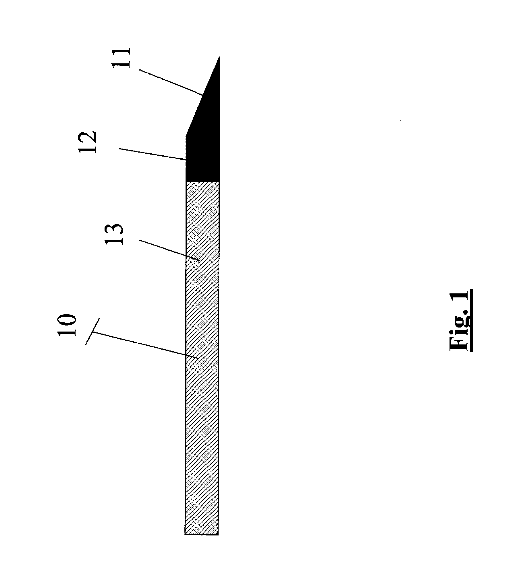
[0028]Reference is now made to FIG. 1, which illustrates a micro-catheter 10, constructed and operative in accordance with a non-limiting embodiment of the present invention.

[0029]The micro-catheter 10 has a lancet tip 11 at a distal end of a distal section 12, and may be constructed with a hollow lumen through its length. The micro-catheter design provides high flexibility, high pushability and high torqueability, despite its small diameter. The distal end section is hard and sharp, designed to penetrate hard and calcified tissues.

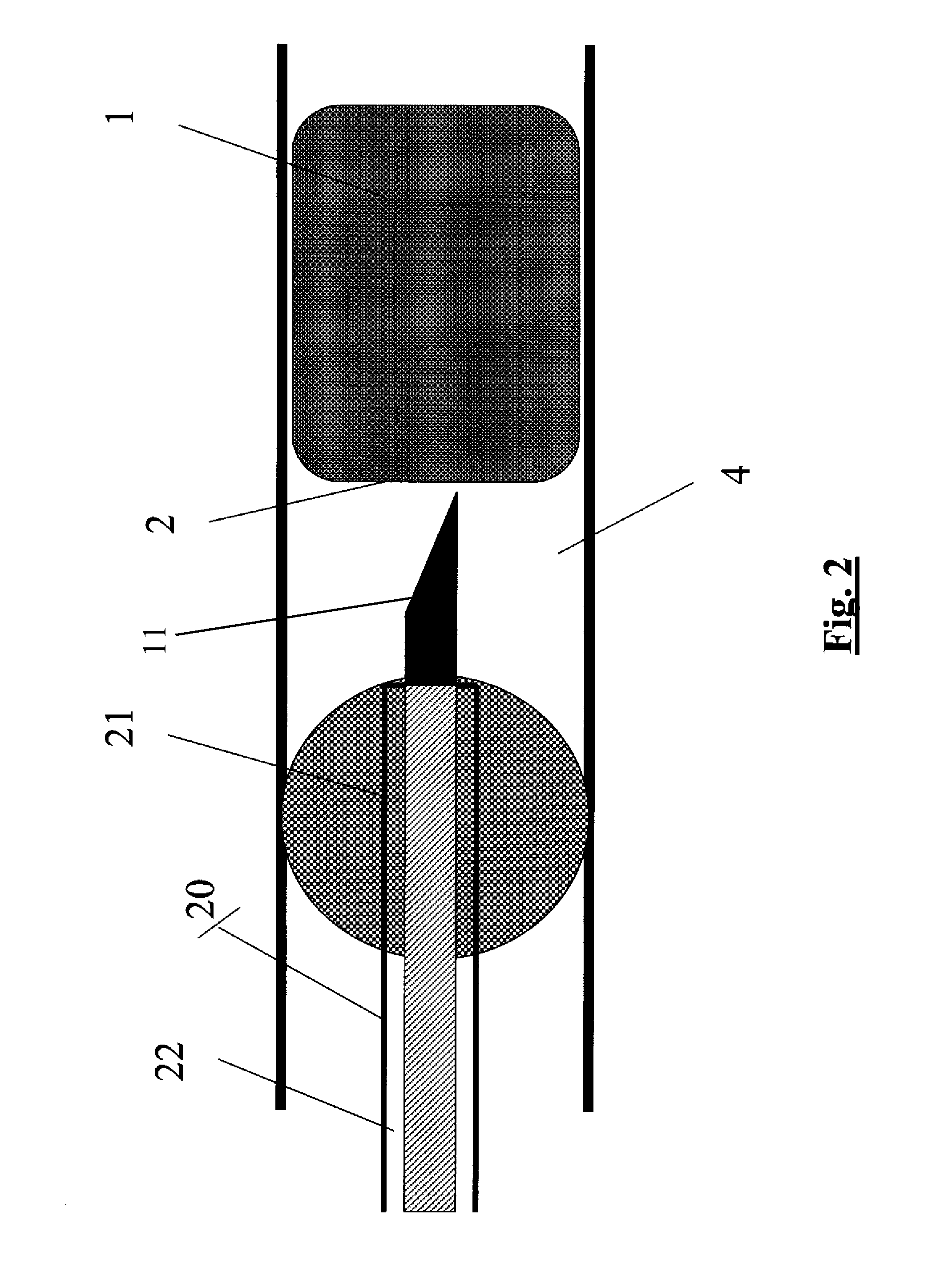
[0030]Reference is now made to FIG. 2. The micro-catheter 10 can be used during CTO percutaneous transluminal recanalization when conventional guide-wires cannot pass an occlusion 1. Usually a proximal cap 2 of the occlusion 1 is penetrated with the hard lancet tip 11, and guide-wires are inserted through the micro-catheter hollow lumen to penetrate the rest of the occlusion. Sometimes the plaque within the diseased blood vessel is hard over the entire le...


PUM


Abstract

A micro-catheter (10) including a hypo-tube including a proximal section (13) and a distal section (12) and a sharp tip (11) formed at a distal end of the distal section (12), characterized in that the proximal section (13) of the micro-catheter (10) is formed with a plurality of cuts (23) which are not perpendicular to a longitudinal axis of the proximal section (13), the cuts (23) being made partially around a circumference of the proximal section (13) with uncut portions separating the cuts (23) from one another.

Description

FIELD OF THE INVENTION[0001]The present invention relates to a micro-catheter having a sharp lancet tip at its distal end, useful, for example, to penetrate hard-calcified tissue and plaque in a vessel.BACKGROUND OF THE INVENTION[0002]Chronic Total Occlusion (CTO) is an arterial vessel blockage that impedes proper blood flow beyond the obstruction. Poor blood flow can lead to insufficient delivery of blood to muscles and vital organs. CTO can occur both in the coronary and peripheral arteries, resulting in disability and even death. The underlying cause of CTO is atherosclerosis.[0003]In order to reverse the effects of CTO, proper blood flow must be reestablished. This must be achieved by either driving through and removing the CTO or creating a bypass around the CTO. Under either scenario, the first step is to “cross” or drive a guidewire through or around the CTO. If the occlusion is relatively new, the plaque is likely to be soft and the guidewire will penetrate and cross the pla...

Claims


Application Information

Patent Timeline
IPC IPC(8): A61B17/34
CPCA61B17/3207A61B2017/22095A61B2017/00252A61B2017/00305A61B2017/22065A61B2017/22071A61B2017/22094A61M25/001A61M25/0013A61M25/0054A61M25/0068A61M25/008A61M25/0084A61M25/065A61M2025/0042A61M2025/0089A61M2025/0197A61M2025/1047A61M2025/1065A61B17/3478
Inventor ROTTENBERG, DANZAKAY, ABISACHER, RON
Owner BOSTON SCI SCIMED INC
Why Eureka
Try Eureka