
Energy efficient street lighting LED luminaire

Inactive Publication Date: 2012-10-18
COURCELLE GUY
View PDF6 Cites 64 Cited by
  • Summary
  • Abstract
  • Description
  • Claims
  • Application Information

AI Technical Summary

Benefits of technology

[0022]It is also an object of the present invention to provide a luminaire wherein the forward cavity section is provided with rib lattice to enhance the strength characteristics thereof.
[0023]It is another object of the present invention to provide a luminaire wherein the luminaire housing and a cover are constructed of 22 ksi yield strength cast aluminum alloy, resisting 5 g forces.
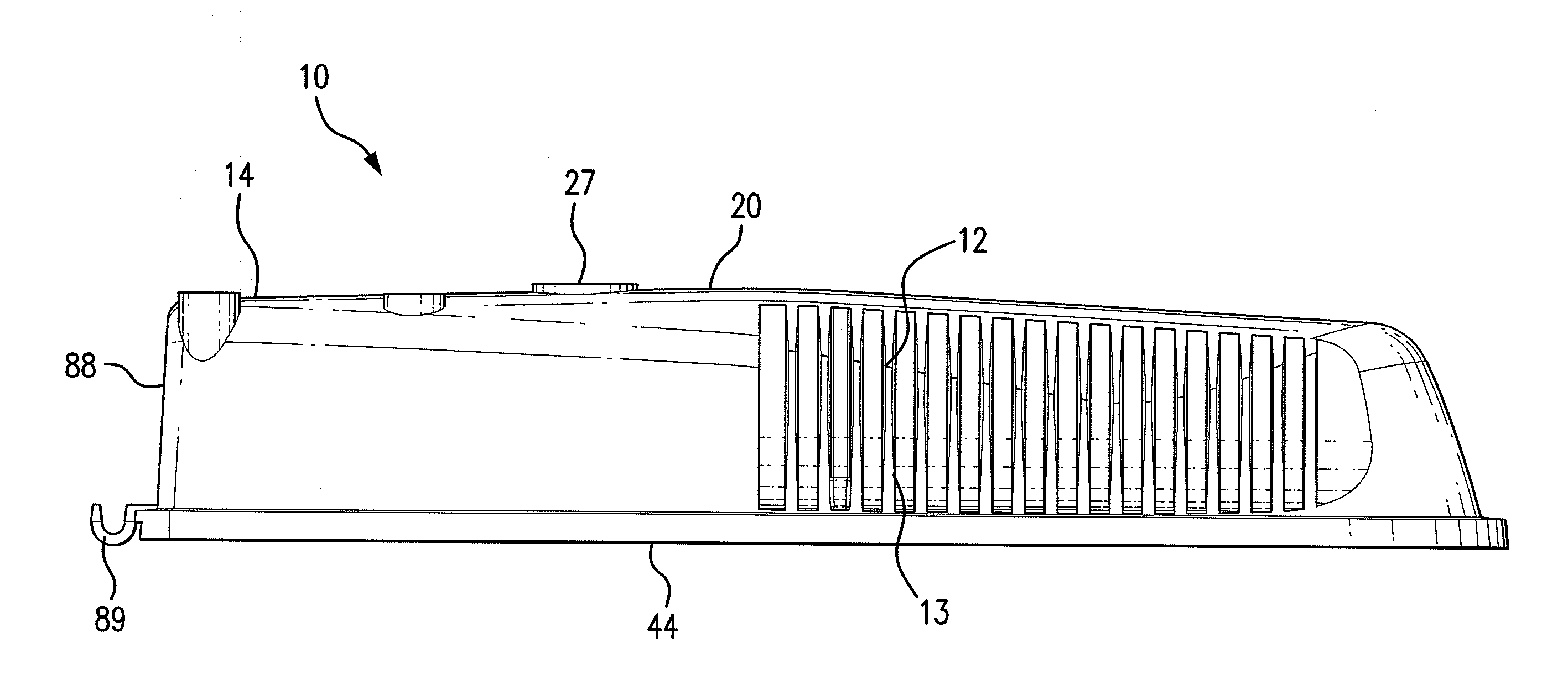
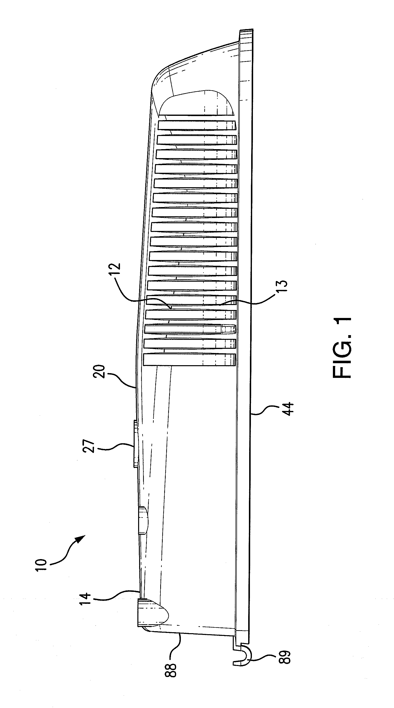
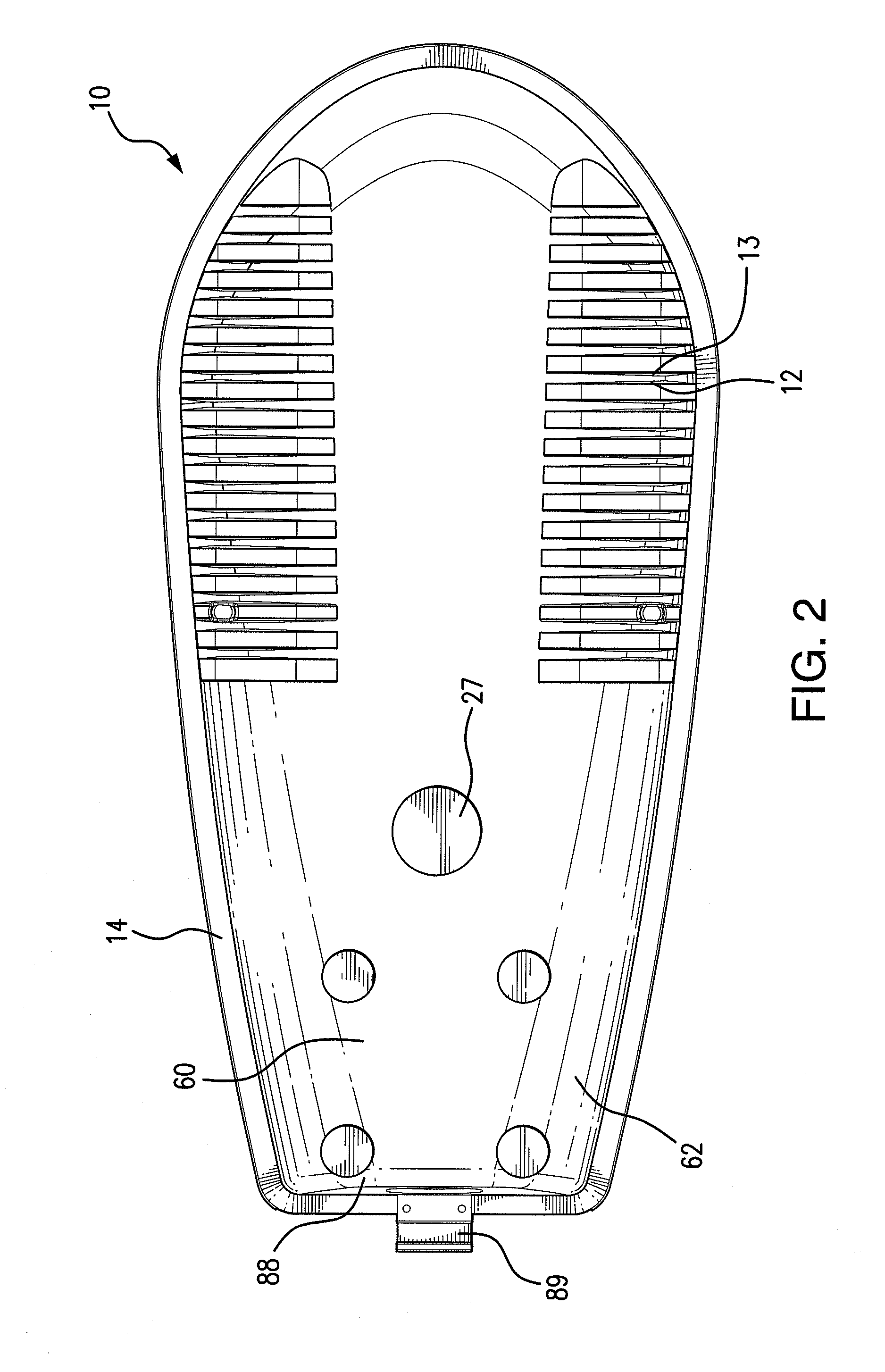
[0024]It is a further object of the present invention to provide a luminaire wherein the heat sink is structured as fins extending outwardly from a primary body of the luminaire housing, and connected ends of the fins share an inner wall of the luminaire housing allowing for effective heat transfer.

Problems solved by technology

So far, most of the high power light emitting diode (LED) luminaires have created many problems.
As a result, a fast penetration of the market has been difficult and these low quality products have hurt the lighting industry.
The challenges that come with the use of LED light sources affect experienced and new lighting manufacturers.
In this technique, the LEDs are often integrated permanently into the fixture, making their replacement difficult or impossible.

Method used


Image

  • Energy efficient street lighting LED luminaire
  • Energy efficient street lighting LED luminaire
  • Energy efficient street lighting LED luminaire

Examples


first embodiment

[0073]As discussed above, the present luminaire 10 also includes a versatile clamping mechanism 24 for attachment of the LED luminaire 10 to the support pole or mast. The housing 14, in the area of the rearward cavity section 36, provides bolting down cradle 52 details allowing the option for the use of alternate clamping mechanisms. Access to the bolting down cradle is provided with the provision of a mast aperture 90 in the end wall 88 of the housing 14. In accordance with a first embodiment, the clamping mechanism 24 uses a four bolt clamp down full size compression cover plate 50 which is secured to the bolting down cradle 52 formed along the inner wall 54 of the housing 14 in the rearward cavity section 36 with bolts 56 to hold to and connect to the post mast as shown in FIG. 6. The full size compression cover plate 50 provides improved non-loosening of the bolts 56 resulting from vibrations.

second embodiment

[0074]In accordance with a second embodiment, and with reference to FIGS. 8, 8A and 8B, the clamping mechanism 24 employs a non-slip compression-split mandrel 58 fitted into the inside diameter of the post mast 94, securing it within the main housing frame of the compression split mandrel 58. The compression fit provides improved non-slippage characteristics of components resulting from vibrations. The compression split mandrel 58 increases the resistance both in the level of rotation and in the extraction of the LED luminaire 10.

[0075]The fixation of a conventional street lighting luminaire to the support pole or mast is made using a clamping system combined with four stainless steel bolts. Since these luminaires are subject to external stresses such as vibrations and gusts of winds, such clamping systems are not designed to prevent tipping luminaires and rotation around the end of the post mast. Because the original positions of the luminaires have been breached, the lighting syst...


PUM


Abstract

An energy-efficient street luminaire includes a luminaire housing having a heat sink in the form of outwardly extending fins integrally formed with the luminaire housing and abutting an LED junction. The luminaire also includes an LED array housed within the luminaire housing and an optical system with a high transmittance glass surrounding the LED array and the LED junction providing for the effective transmission of light generated by the LED array. An electronic driver is coupled to the LED arrays for controlling the transmission of electricity thereto.

Description

CROSS REFERENCE TO RELATED APPLICATION[0001]This application claims the benefit of U.S. Provisional Patent Application Ser. No. 61 / 475,952, entitled “ENERGY EFFICIENT STREET LIGHTING LED LUMINAIRE,” filed Apr. 15, 2011.BACKGROUND OF THE INVENTION[0002]1. Field of Invention[0003]The invention relates to street lighting LED luminaires.[0004]2. Description of the Related Art[0005]LED products for street lighting have been appearing on the market continuously. So far, most of the high power light emitting diode (LED) luminaires have created many problems. As a result, a fast penetration of the market has been difficult and these low quality products have hurt the lighting industry. The challenges that come with the use of LED light sources affect experienced and new lighting manufacturers. In the past, each step of a luminaire design could be undertaken separately. It is completely different when applying LED technology to the production of luminaires.[0006]Currently, there are two majo...

Claims


Application Information

Patent Timeline
IPC IPC(8): F21V5/04F21V29/00F21V17/10F21V31/00F21V31/03F21V21/00F21V17/12
CPCF21V31/00F21S8/08F21V15/01F21V17/107F21V21/116F21V29/89F21Y2101/02Y02B20/72F21V29/507F21V29/76F21W2131/103F21Y2115/10
Inventor COURCELLE, GUY
Owner COURCELLE GUY
Learn More