
In-Memory Processing for a Data Warehouse

a data warehouse and in-memory technology, applied in the field of data processing, can solve the problems of delay in data processing time in a data warehouse, time delay associated with accessing data stored in tables of a database management system,

Active Publication Date: 2012-10-11
SAP AG +1
View PDF3 Cites 43 Cited by
  • Summary
  • Abstract
  • Description
  • Claims
  • Application Information

AI Technical Summary

Benefits of technology

[0018]In one embodiment, each of the first data records comprises a record mode field specifying how one or more corresponding data fields of the first data records are to be recorded in the first data storage structure.

Problems solved by technology

One problem with the above architecture for data warehousing is the time delay associated with accessing data stored in tables of a database management system.
These are just examples of what are sometimes referred to as database management system “round trips”, which are time consuming and may delay data processing time in a data warehouse.

Method used


Image

  • In-Memory Processing for a Data Warehouse
  • In-Memory Processing for a Data Warehouse
  • In-Memory Processing for a Data Warehouse

Examples


example

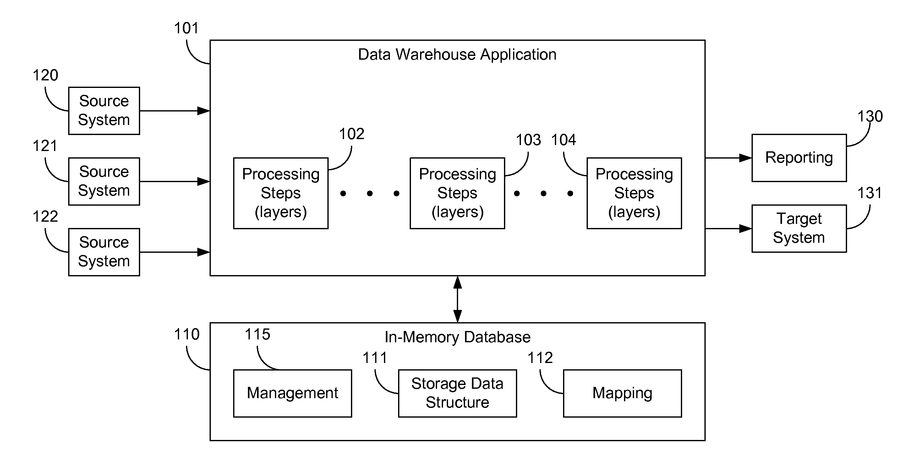
[0037]FIG. 3A illustrates a data warehouse and an in-memory database according to another embodiment of the present invention. In this example, a data warehouse application 301 stores and retrieves data from an in-memory database 310. A data source 302 may provide the data to be stored. Table 1 shows an example of three data records from data source 302 to be stored in in-memory database 310.

TABLE 1RECORDNUMBERCUSTOMERAMOUNTRECORDMODE1ABC Co.10New2XYZ Co.5New3123 Co.6New

[0038]Each data record in this example includes a record number, customer, and amount (e.g., of items purchased). In this example, the data records include a record mode field. A record mode field may be used to specify how one or more corresponding data fields of the data records are to be recorded in the first data storage structure. In this example, the record mode is “New”, which indicates that the data is to be recorded as a new record. Other record modes may include “After Image”, indicating that the data field...

example hardware

[0066]FIG. 6 illustrates hardware of a special purpose computing machine configured with a process according to one embodiment of the present invention. The following hardware description is merely one example. It is to be understood that a variety of computers topologies may be used to implement the above described techniques. An example computer system 610 is illustrated in FIG. 6, which shows components of a single computer. Computer system 610 includes a bus 605 or other communication mechanism for communicating information, and one or more processor(s) 601 coupled with bus 605 for processing information. Computer system 610 also includes a memory 602 coupled to bus 605 for storing information and instructions to be executed by one or more processor(s) 601, including information and instructions for performing the techniques described above, for example. This memory may also be used for storing variables or other intermediate information during execution of instructions to be ex...


PUM


Abstract

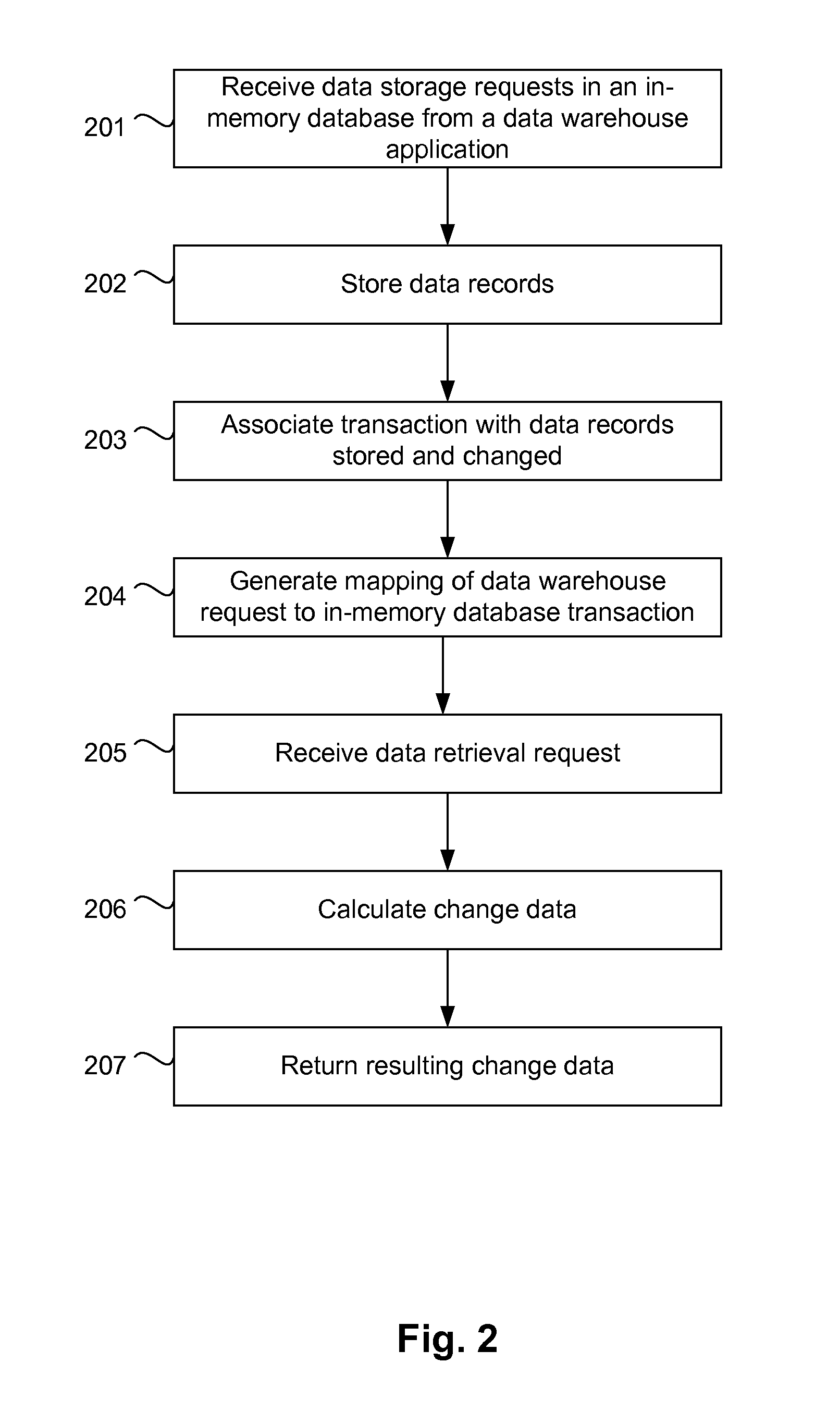
Embodiments of the present invention include in-memory processing for data warehouse applications. In one embodiment, data records from a data warehouse application are stored in a data storage structure of an in-memory database. Data received from the data warehouse may be stored in a queue and loaded into the data storage structure according to predefined rules. Stored data records are associated with in-memory database transactions that caused the stored data record to be stored, and may further be associated with transactions that caused the stored data records to be changed. A mapping is generated to associate requests from the data warehouse application with in-memory database transactions. The data warehouse application may retrieve data in a change data format calculated on-the-fly.

Description

BACKGROUND[0001]The present invention relates to data processing, and more particularly, to systems and methods of processing data for a data warehouse using in-memory data storage.[0002]Data warehouses are used to store large volumes of data for analysis. Data warehouses receive data from a variety of source systems and make the data available for a wide variety of complex analytic queries. As data is received in a data warehouse, the data may be repeatably stored and transformed as the data is massaged into a form that supports the desired analysis. In some applications, data is received in a very granular level and processed across multiple layers, which may transform, merge, consolidate and aggregate data according to the particular needs of an organization.[0003]According to some architectures, as data is received and processed by a data warehouse, data may be stored in a database management system in one or more data containers. For example, the data warehouse may be a softwar...

Claims


Application Information

Patent Timeline
Patent Type & Authority Applications(United States)
IPC IPC(8): G06F17/30
CPCG06F17/30563G06F16/254
Inventor HERMANN, ALEXANDERWINSEMANN, THORSTENHEIDEL, MARTINTHUMFART, ANDREASBADER, ANDREAS
Owner SAP AG
Learn More