
Recording tape cartridge

Inactive Publication Date: 2012-10-04
FUJIFILM CORP
View PDF28 Cites 0 Cited by
  • Summary
  • Abstract
  • Description
  • Claims
  • Application Information

AI Technical Summary

Benefits of technology

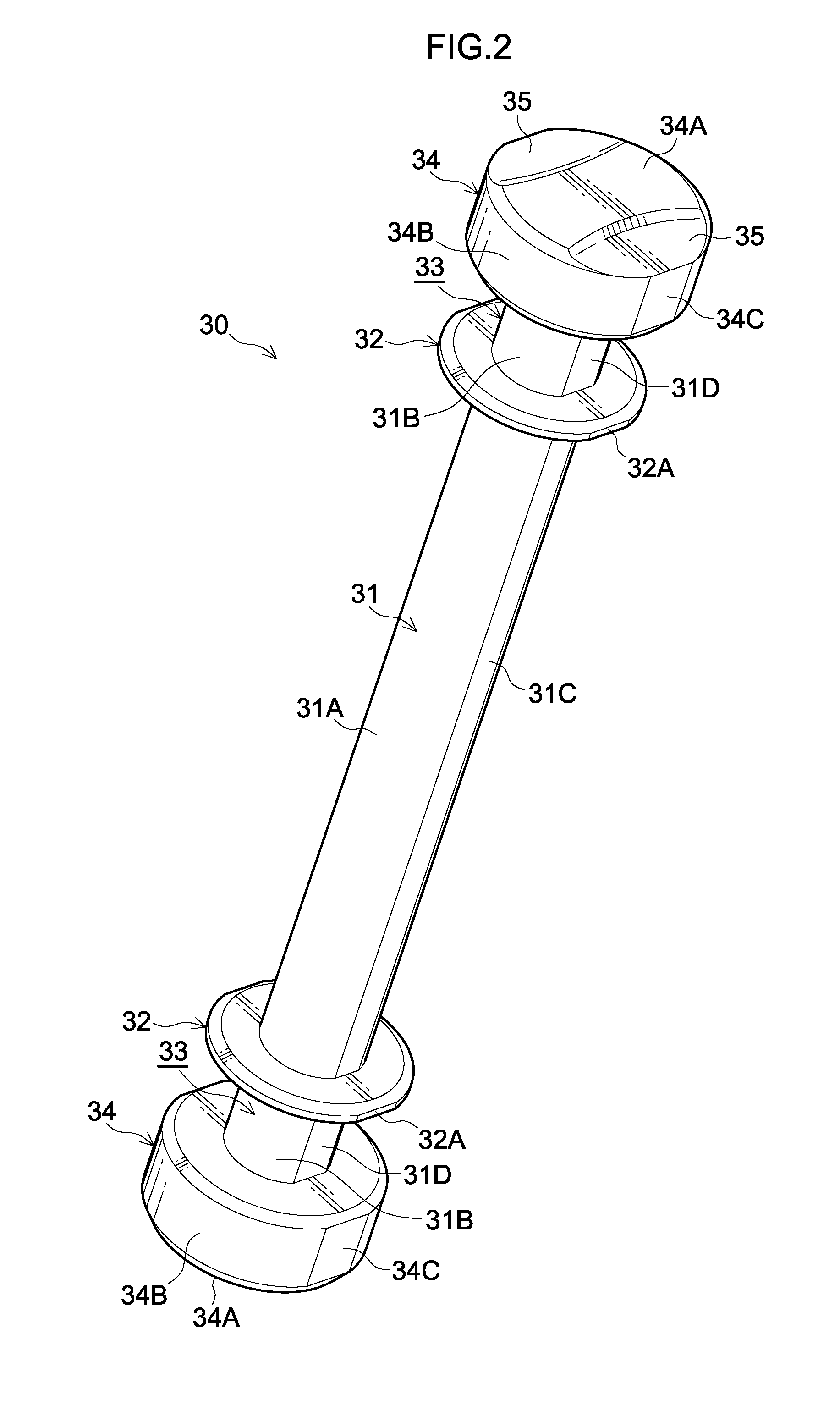
[0010]According to the first aspect of the invention, the leader pin that is fabricated by die-casting and at which the flat surface portions are formed at parting line portions is attached to the free end portion of the recording tape or the sheet-form member connected to the recording tape such that the angle of the leader pin with respect to the tension direction of the free end portion is the angle such that the flat surface portions formed at the both end portions do not come into contact with the plate spring. Therefore, the leader pin may be properly retained by the plate spring.
[0014]According to the third aspect of the invention, because the width of the flat surface portion formed at the head portion is greater than the width of the flat surface portion formed at the main body portion, when the free end portion of the recording tape or the sheet-form member connected to the recording tape is being attached to the leader pin, the leader pin can be positioned in the circumferential direction thereof by the flat surface portions at the head portions being placed face down on a flat face (for example, of a support pedestal). Therefore, an operation of attaching the free end portion to the leader pin is easier.
[0016]According to the fourth aspect of the invention, a leader pin with an excellent low-friction characteristic is provided.
[0018]According to the fifth aspect of the invention, a plate spring with an excellent low-friction characteristic is provided.

Problems solved by technology

When such flashing or stepped edge is formed in the axial direction, there is a risk of the free end portion of the recording tape or leader tape connected to the recording tape being damaged by the flashing or stepped edge.
However, if the leader pin is attached to the free end of the recording tape or the leader tape connected to the recording tape in such a way that distal end portions of a plate spring, which retain the both end portions of the leader pin when the leader pin is accommodated in the case, are in contact with a flat surface portion formed at a parting line portion at the both end portions, spring force of the distal end portions of the plate spring on the both end portions of the leader pin accommodated in the case may be inconsistent.

Method used


Image

  • Recording tape cartridge
  • Recording tape cartridge
  • Recording tape cartridge

Examples


Embodiment Construction

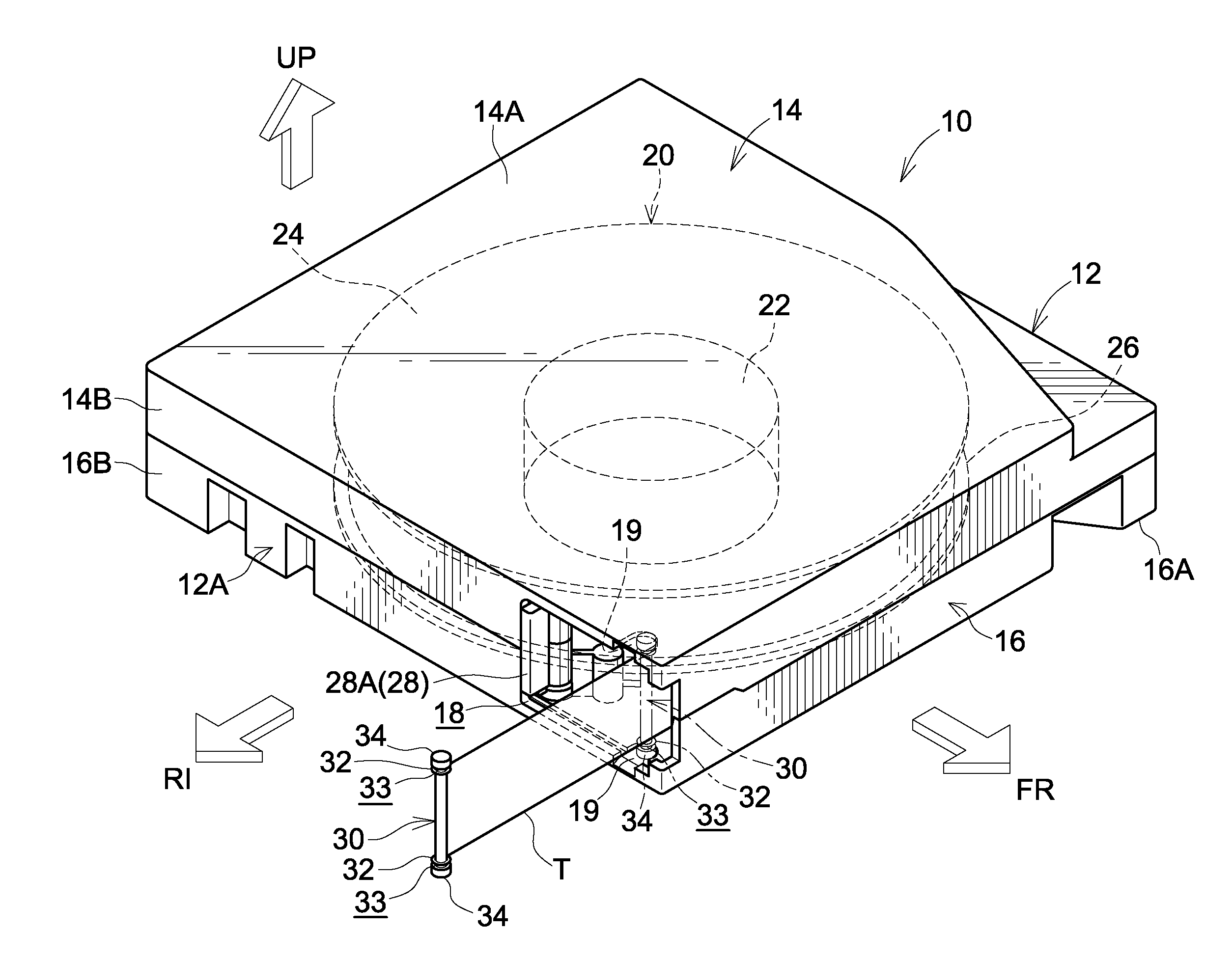
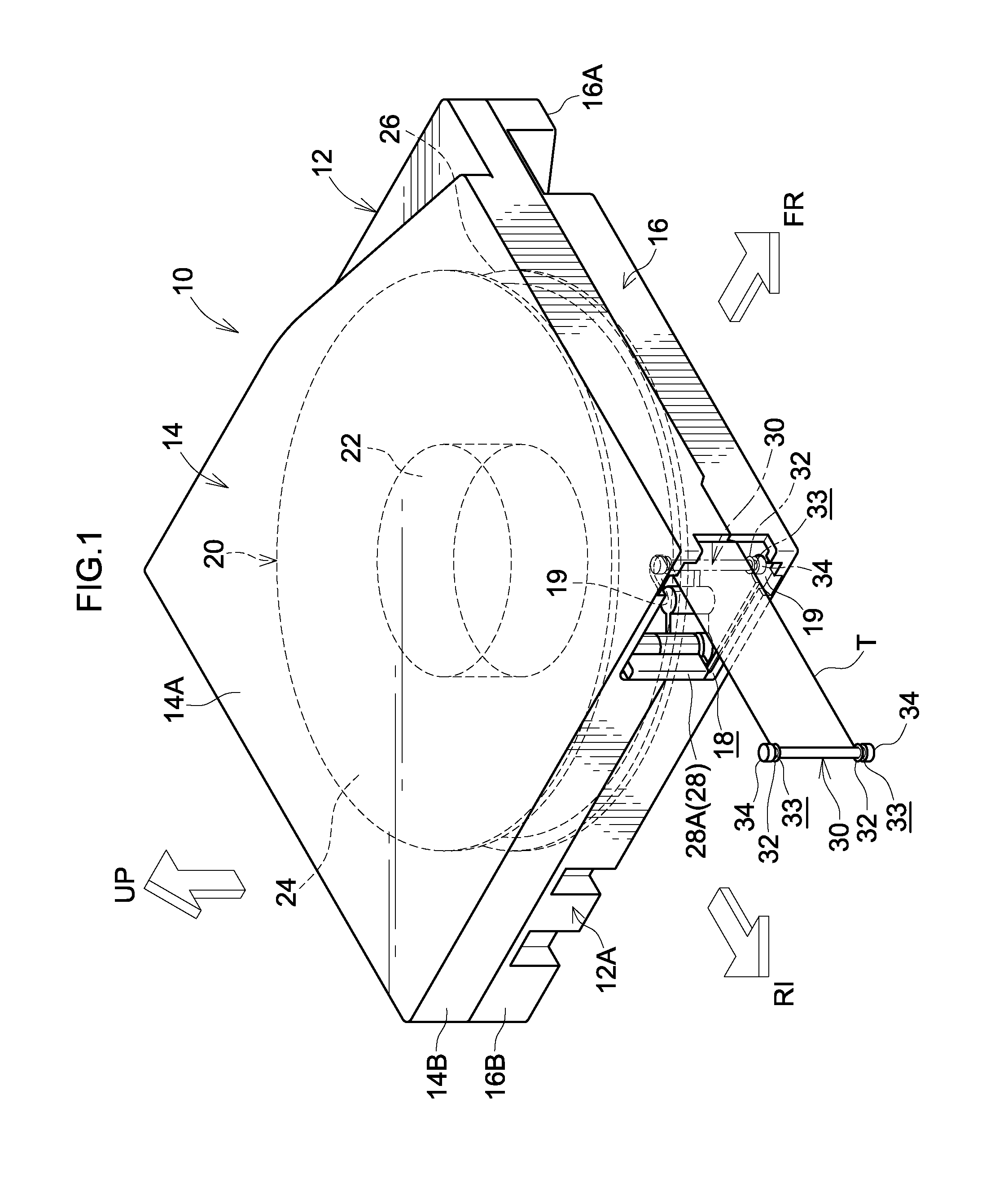
[0043]Herebelow, an exemplary embodiment relating to the present invention is described in detail in accordance with the attached drawings. For convenience of description, in FIG. 1, a direction of loading of a recording tape cartridge 10 into a drive device is indicated by the arrow FR and is referred to as a forward direction (front side) of the recording tape cartridge 10. The direction of an arrow RI that is orthogonal to the arrow FR is referred to as a rightward direction (right side). A direction orthogonal to the arrow FR and the arrow RI is indicated by the arrow UP and is referred to as an upward direction (upper side) of the recording tape cartridge 10. First, overall structure of the recording tape cartridge 10 is described.

[0044]As illustrated in FIG. 1, the recording tape cartridge 10 includes a substantially rectangular box-shaped case 12. A peripheral wall 14B is provided standing from a peripheral edge of a ceiling plate 14A of an upper case 14 that is fabricated of...


PUM


Abstract

A leader pin is fabricated by die-casting, is attached to a free-end portion of a recording tape, and is drawn out through an opening formed in a case. A plate spring retains axial direction both end portions of the leader pin such that the leader pin does not fall from inside the case. When the leader pin is being mounted at or removed from the case, the plate spring is pushed by the end portions and resiliently deforms, and allows the mounting or removal operation of the leader pin. A flat surface portion is formed at the leader pin so as to remove parting line portion of the leader pin. The leader pin is attached to the free-end portion at an angle relative to a tension direction of the free-end portion, such that the flat surface portions formed at the end portions do not contact with the plate spring.

Description

CROSS-REFERENCE TO RELATED APPLICATION[0001]This application claims priority under 35 USC 119 from Japanese Patent Application No. 2011-079243 filed Mar. 31, 2011, the disclosure of which is incorporated by reference herein.BACKGROUND OF THE INVENTION[0002]1. Field of the Invention[0003]The present invention relates to a recording tape cartridge that accommodates a single reel onto which a recording tape such as a magnetic tape or the like is wound, principally for use as a recording / replaying medium for computers and the like.[0004]2. Related Art[0005]Heretofore, a recording tape cartridge has been known in which a recording tape such as a magnetic tape or the like, which is used as a data recording / replaying medium (data backup) for computers and the like, is wound on a reel and this reel is singly accommodated in a case. A leader pin, for a drawing member of a drive device to engage with and draw out, is attached to a free end portion of the recording tape or of a leader tape con...

Claims


Application Information

Patent Timeline
IPC IPC(8): G11B23/107
CPCG11B23/107
Inventor HIRAGUCHI, KAZUO
Owner FUJIFILM CORP
Learn More