
Air conditioner for vehicle

a technology for air conditioners and vehicles, applied in the field of air conditioners for vehicles, can solve the problems of a certain length of time for the air temperature of the vehicle interior, low air temperature blown to the vehicle interior, etc., and achieve the effect of efficient air heating and efficient use of refrigeran

Inactive Publication Date: 2012-10-04
CALSONIC KANSEI CORP
View PDF7 Cites 3 Cited by
  • Summary
  • Abstract
  • Description
  • Claims
  • Application Information

AI Technical Summary

Benefits of technology

The present invention relates to an air conditioner for a vehicle that can heat the air in the vehicle interior using the cooling water of the engine. The air conditioner has separate circuits for cooling and heating, and a three-way solenoid valve that can switch between the two cycles. The invention aims to prevent hunting (when the compressor is operated for heating air in an overlapping temperature range of both cooling and heating) and improve the efficiency of the air conditioner by selectively executing the normal airconditioning mode or the auxiliary air heating mode based on the cooling water temperature, outside air temperature, and inside air temperature. The invention also includes a water temperature sensor, an outside air temperature sensor, and an inside air temperature sensor to detect the cooling water temperature, outside air temperature, and inside air temperature.

Problems solved by technology

However, since the air heating unit uses the engine cooling water, the temperature of the cooling water remains low for a while after an engine start so that the air temperature blown to the vehicle interior is also low.
Thus, it may take a certain length of time for the air temperature of the vehicle interior to reach a temperature at which occupants can feel comfortable.

Method used


Image

  • Air conditioner for vehicle
  • Air conditioner for vehicle
  • Air conditioner for vehicle

Examples


embodiment

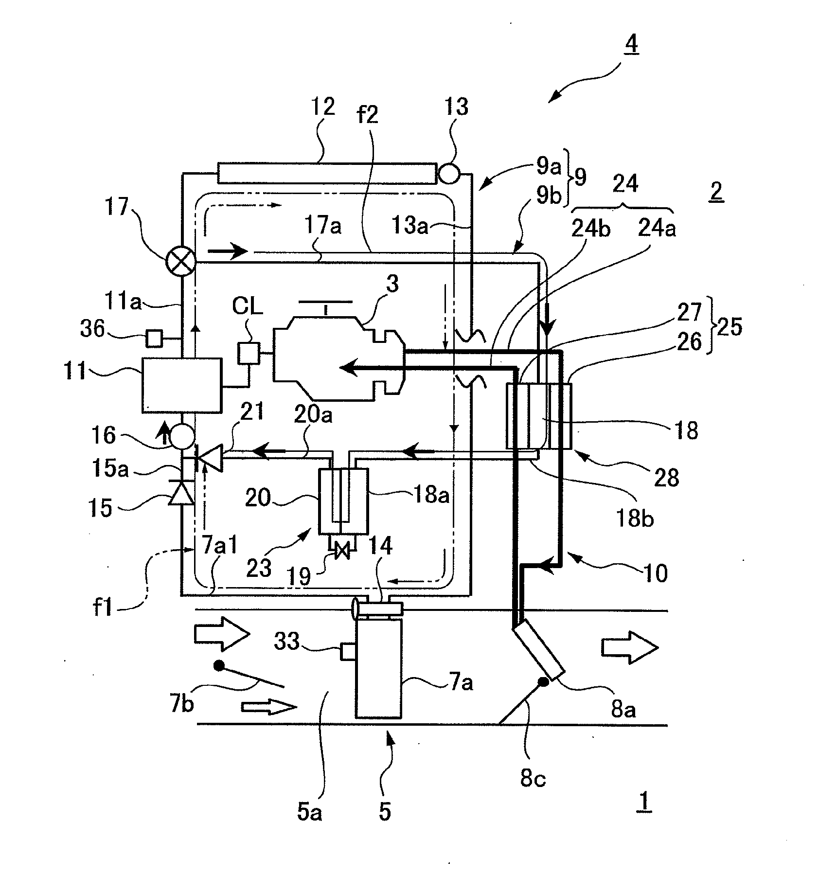
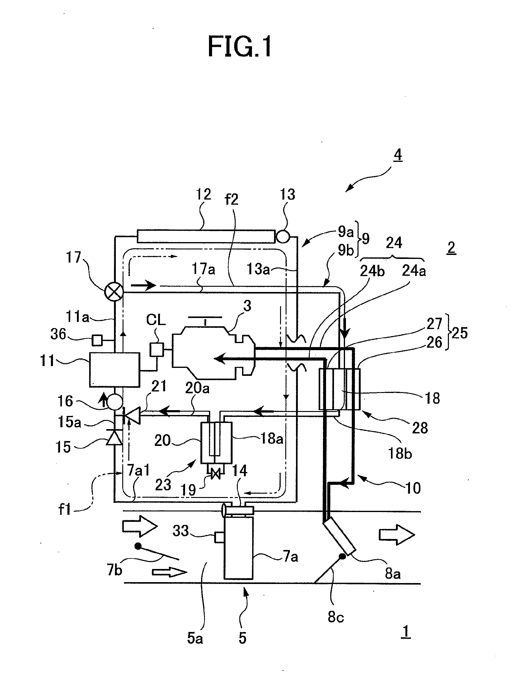
[0038]FIG. 1 shows a vehicle (automobile) interior 1, an engine compartment 2, a water cooled engine (vehicle drive unit) 3 provided in the engine compartment 2, and an air conditioner for vehicle 4 according to the present invention.

[0039]The engine 3 includes a water jacket (not shown).

[0040]The water jacket has an engine cooling water passage (cooling water passage) around a combustion chamber (heat generator) of the engine 3. The cooling water is circulated through this passage to absorb the heat from the combustion chamber of the engine 3 and cool the engine 3.

[0041]An instrument panel (not shown) is provided on the front side of the vehicle interior 1. An airconditioning unit 5 constituting the vehicle air conditioner 4 is provided in the instrument panel.

5>

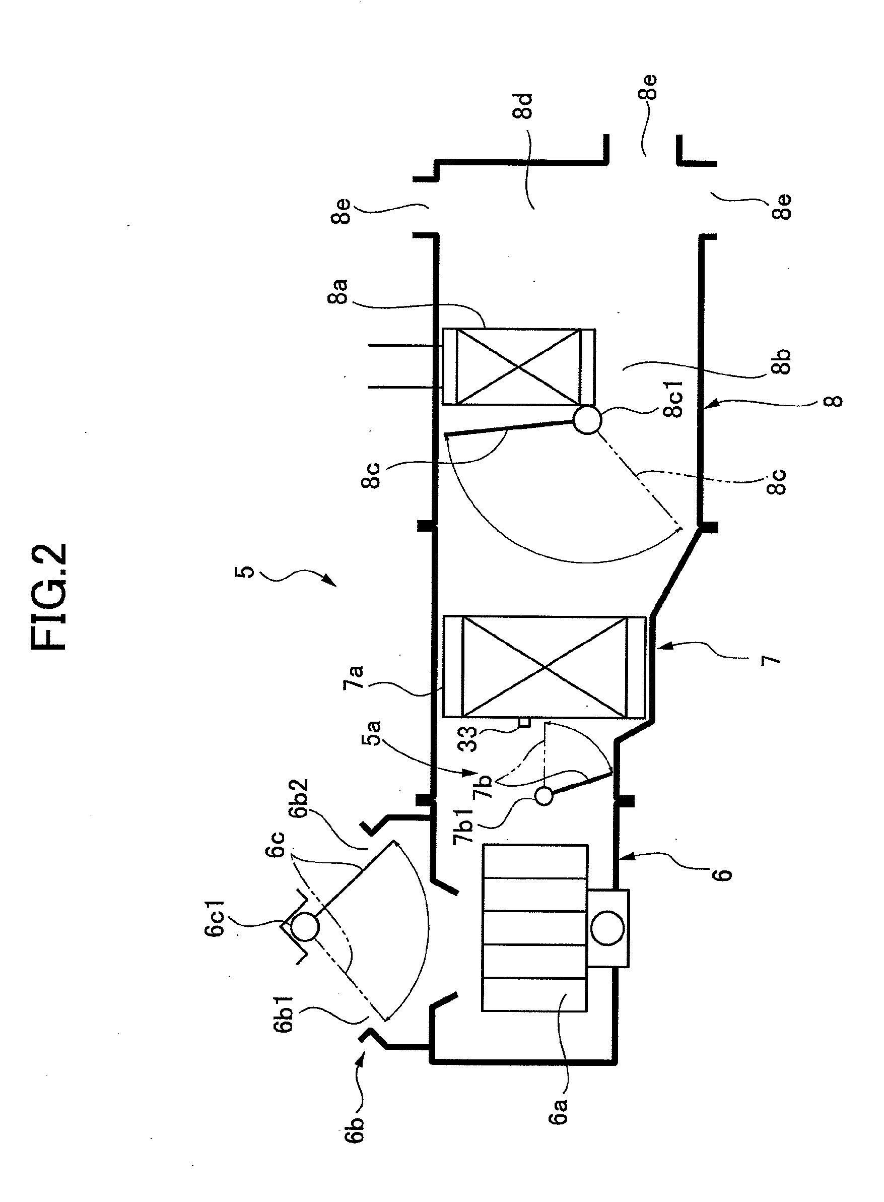
[0042]In FIG. 2 the airconditioning unit 5 includes a blower unit 6, a cooler unit 7, and a heater unit 8.

[0043]An air passage 5a is formed in the cooler unit 7 and the heater unit 8 to connect them.

[0044]The air from the b...


PUM


Abstract

Provided is an air conditioner for a vehicle which can prevent the controls over cooling cycle and heating cycle from interfering with each other and thereby prevent hunting between the cooling and heating cycles even when a compressor is operated to perform the heating cycle in an overlapping temperature range where air cooling and air heating are both required. An air conditioner (4) for a vehicle includes a refrigerant circulation circuit (9b) for air heating to circulate a refrigerant, and a control unit (29) to selectively perform a normal air conditioning mode in which a normal cooling operation is feasible by circulating the refrigerant through a refrigerant circulation circuit (9a) for air cooling and an auxiliary heating mode in which an auxiliary heating operation is performed by circulating the refrigerant through the refrigerant circulating circuit (9b) for air heating.

Description

TECHNICAL FIELD[0001]The present invention relates to an air conditioner for a vehicle to heat the air in a vehicle interior using the heat from a cooling water.BACKGROUND ART[0002]A conventional vehicle air conditioner is generally comprised of an air heating unit using the heat from an engine cooling water and an air cooling unit using a refrigeration cycle.[0003]In the air heating unit, a high-temperature engine cooling water having absorbed heat from the engine is circulated inside a heater core in an instrument panel to heat the air by the heat from the heater core and blow the heated air from an outlet of the instrument panel for heating the air in the vehicle interior.[0004]However, since the air heating unit uses the engine cooling water, the temperature of the cooling water remains low for a while after an engine start so that the air temperature blown to the vehicle interior is also low.[0005]Thus, it may take a certain length of time for the air temperature of the vehicle...

Claims


Application Information

Patent Timeline
Patent Type & Authority Applications(United States)
IPC IPC(8): F25B29/00F25B13/00
CPCB60H1/00807B60H1/00892B60H1/00885
Inventor NAKAJO, KAZUOTAKEI, TOSHIHIROSOMA, HIROSHI
Owner CALSONIC KANSEI CORP
Learn More