
Clutch with built-in torsional vibration damper

Active Publication Date: 2012-10-04
KAWASAKI MOTORS LTD
View PDF8 Cites 9 Cited by
  • Summary
  • Abstract
  • Description
  • Claims
  • Application Information

AI Technical Summary

Benefits of technology

[0009]The present invention has been devised with a view to substantially eliminating the above discussed problems and inconveniences and is intended to provide a torsional vibration damper equipped clutch, that is, a clutch having a torsional vibration damper built therein, which is effective to suppress the torsional vibration of the drive shaft.

Problems solved by technology

It is, however, often experienced that during a semi-clutch period subsequent to the engagement of the clutch to the complete engagement of the same, a torsional vibration tends to be generated in, for example, a drive shaft and / or a clutch drum used to connect between the combustion engine and a load such as, for example, cutter blade.
However, once the clutch is disengaged, the rotation of the cutter blade is lowered and the rotational speed of the combustion engine increases again, causing the clutch to be engaged again.
At this time, the combustion engine is loaded with the cutter blade, accompanied by reduction in rotational speed of the combustion engine, which subsequently results in re-disengagement of the clutch.
Considering that the coupling shaft has a function as the connecting member for fixing the flywheel to the output shaft of the combustion engine, loosening of the coupling shaft in the manner described above results in a rattling motion taking place in the threaded connection between the coupling shaft and the output shaft of the combustion engine, accompanied by generation of obnoxious sounds brought about by vibrations of the flywheel.
Also, the clutch may become unstable to such an extent as to amplify the vibrations.

Method used


Image

  • Clutch with built-in torsional vibration damper
  • Clutch with built-in torsional vibration damper
  • Clutch with built-in torsional vibration damper

Examples


Embodiment Construction

[0027]Some preferred embodiments of the present invention will now be described in detail with reference to the accompanying drawings.

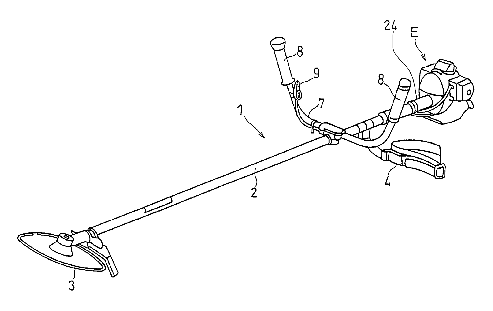
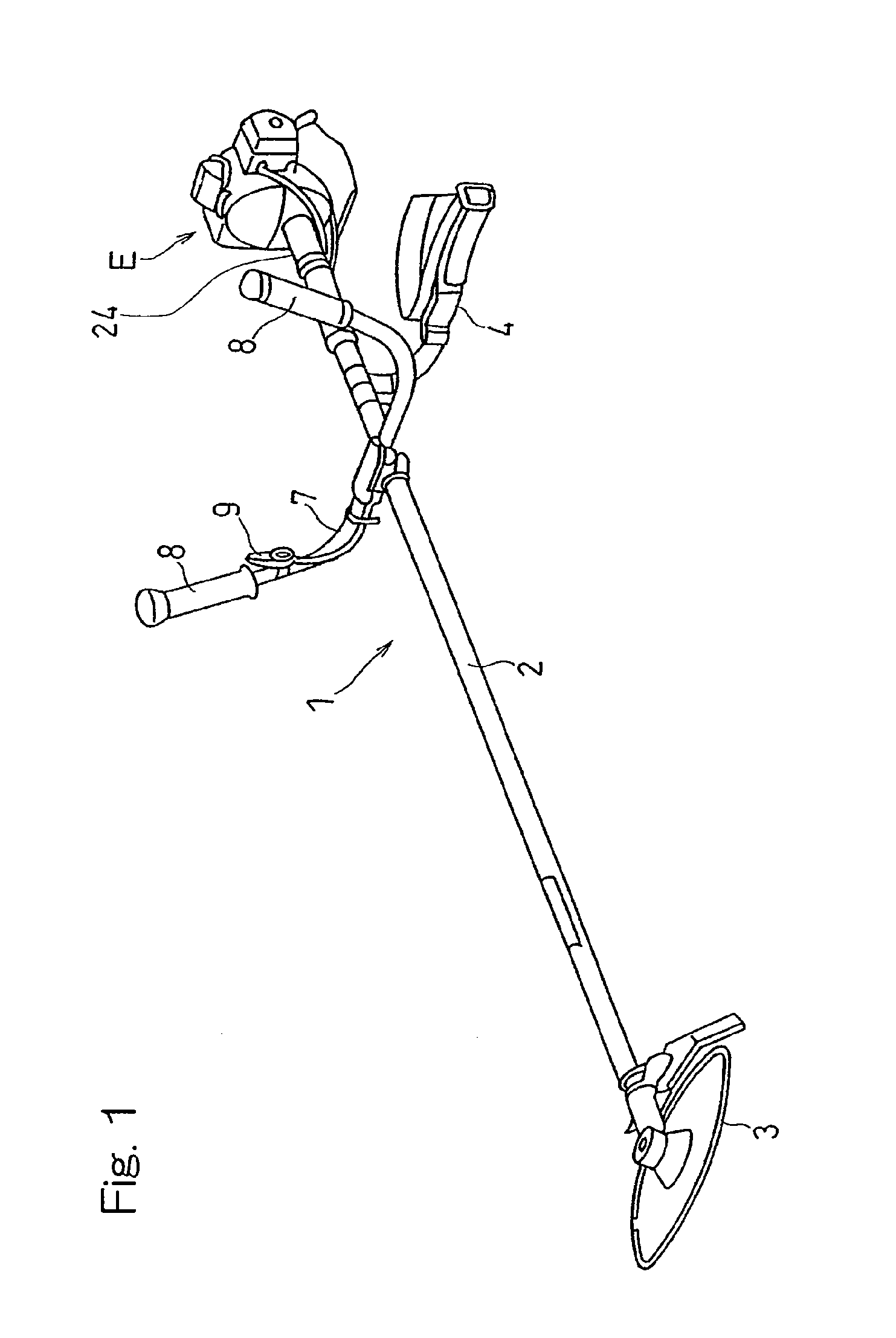
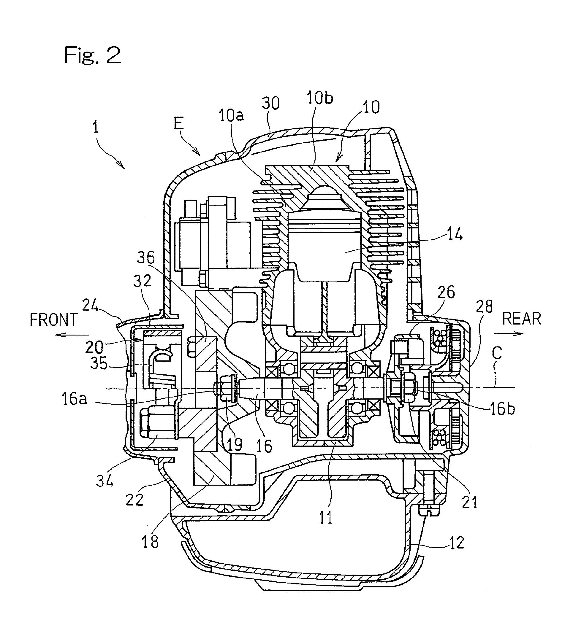
[0028]Referring first to FIGS. 1 to 4, there is shown a brush cutter 1, which is one of portable work machines and which has a compact combustion engine E equipped with a damper equipped clutch designed in accordance with a first preferred embodiment of the present invention. The illustrated brush cutter 1 has the combustion engine E fitted to a base end portion of an elongated metallic main tube 2 made of, for example, an aluminum alloy and also has a rotary cutter blade 3 fitted as a work tool to a free end of the main tube 2 remote from the combustion engine E. The main tube 2 has a hollow defined therein over the length thereof, and a drive shaft 6 made of, for example, iron is drivingly inserted within the hollow of the main tube 2 as best shown in FIG. 3. The drive shaft 6 has an proximal end 6a drivingly coupled with the combustion engine E thr...


PUM


Abstract

A torsional vibration damper equipped clutch (20) for a combustion engine (E) includes a clutch drum (32), coupled with a cutter blade (3) through a drive shaft (6), a clutch shoe (34) connected with a crankshaft (16) of the combustion engine (E) and capable of being connected with the clutch drum (32) by the effect of a centrifugal force. The clutch (20) further includes a flywheel (18) fixed to the crankshaft (16) by means of a nut (19), and a holder (36) connected with the flywheel (18) for relative movement in a circumferential direction through a helical compression spring (50). The clutch shoe (34) is supported by the holder (36), and a stopper structure (56) is provided between the flywheel (18) and the holder (36) for transmitting a rotational force of the combustion engine (E) to the holder (36).

Description

CROSS REFERENCE TO THE RELATED APPLICATION[0001]This application is based on and claims Convention priority to Japanese patent application No. 2011-077662, filed Mar. 31, 2011, the entire disclosure of which is herein incorporated by reference as a part of this application.BACKGROUND OF THE INVENTION[0002]1. Field of the Invention[0003]The present invention relates to a centrifugal clutch for use mainly in a compact combustion engine used to drive a work machine such as, for example, a brush cutter.[0004]2. Description of Related Art[0005]In the compact combustion engine of a type utilizing a centrifugal clutch, the clutch starts engaging when the combustion engine attains the rotational speed of, for example, 3,800 rpm and is completely engaged when the combustion engine attains the rotational speed of about 7,000 rpm. It is, however, often experienced that during a semi-clutch period subsequent to the engagement of the clutch to the complete engagement of the same, a torsional vib...

Claims


Application Information

Patent Timeline
IPC IPC(8): F16D43/14B27B5/38A01D34/90
CPCA01D34/905F16D2043/145F16D43/14F16F15/12313F16F15/1234
Inventor YUASA, TSUNEYOSHI
Owner KAWASAKI MOTORS LTD
Learn More