
Microtube with lid opening mechanism

a technology of opening mechanism and microtube, which is applied in the field of microtubes, can solve the problems of contaminating the underside of the lid and/or the user's hands affecting the use of the lid, etc., and achieves the effect of easy misplacement, dropping or losing

Inactive Publication Date: 2012-09-27
MICROSTEIN LLC
View PDF2 Cites 0 Cited by
  • Summary
  • Abstract
  • Description
  • Claims
  • Application Information

AI Technical Summary

Benefits of technology

[0019]In another preferred embodiment the flange also finds use as a handle by which the microtube can be easily handled, eg for insertion / removal from laboratory apparatus.
[0026]The flange is preferably of a length which allows it to be conveniently grasped by the handler thereby allowing for rapid and easy removal of the tube, for example, from a rotor. Removal can be accomplished by grasping the flange with the thumb and forefinger thereby making the operation one handed since forceps or other grasping devices are not required.
[0028]By providing a microtube that comprises a lid having a flange extending outwardly from the lid so that mechanical force applied downwardly to the upper surface of the flange opens the lid, the handler is able to open the tube with ease and using only one hand. This means that the handler is able to handle other tubes whilst keeping other instruments e.g. for dispensing, in the other hand thereby eliminating the risk of contamination of the tubes or instruments by contact with the work surface.
[0029]Since the lid of the microtube is opened by the application of mechanical force applied downwardly to the upper surface of the flange, the open lid may act as a shield between the object applying the mechanical force, for example the thumb of the handler, and the tube opening thereby avoiding contamination of the tube or sample which might otherwise occur with conventional tubes.
[0033]It is preferred that the flange is attached to the lid within the half of the lid proximal to the hinge. This location of the flange provides leverage to facilitate the opening of the container.
[0034]In a third aspect, the invention provides a method for opening a closed microtube according to the invention, the method comprising applying pressure to a upper surface of the flange to break the closing / sealing contact between the lid and the container, such that the lid and the flange are pivoted about the hinge to open the container. Preferably, this method allows for opening a microtube of the invention without contaminating the inside of the lid, container or the container contents

Problems solved by technology

One-handed operation can be attempted, however, in practice this is very difficult and often results in contamination of the underside of the lid and / or the user's hands.
The movements used put a strain on the thumb, causing chaffing, swelling, bruising and associated discomfort.
After extended use this can lead to repetitive strain injury.
In addition these tools are easily misplaced, dropped or lost.
This can cause contamination and is physically ackward.
If this operation is attempted one-handed, it also can cause contamination to the tube and the chaffing and bruising mentioned above.
Such operation can lead over time to repetitive strain injury.
However, since microcentrifuge tubes are routinely used as containers for the storage of toxic and radioactive chemicals, tubes whose lid opens toward the face and body of the user are undesirable due to the risk of contamination of the user by the contents of the tube spraying out when the lid is snapped open.

Method used


Image

  • Microtube with lid opening mechanism
  • Microtube with lid opening mechanism

Examples


Embodiment Construction

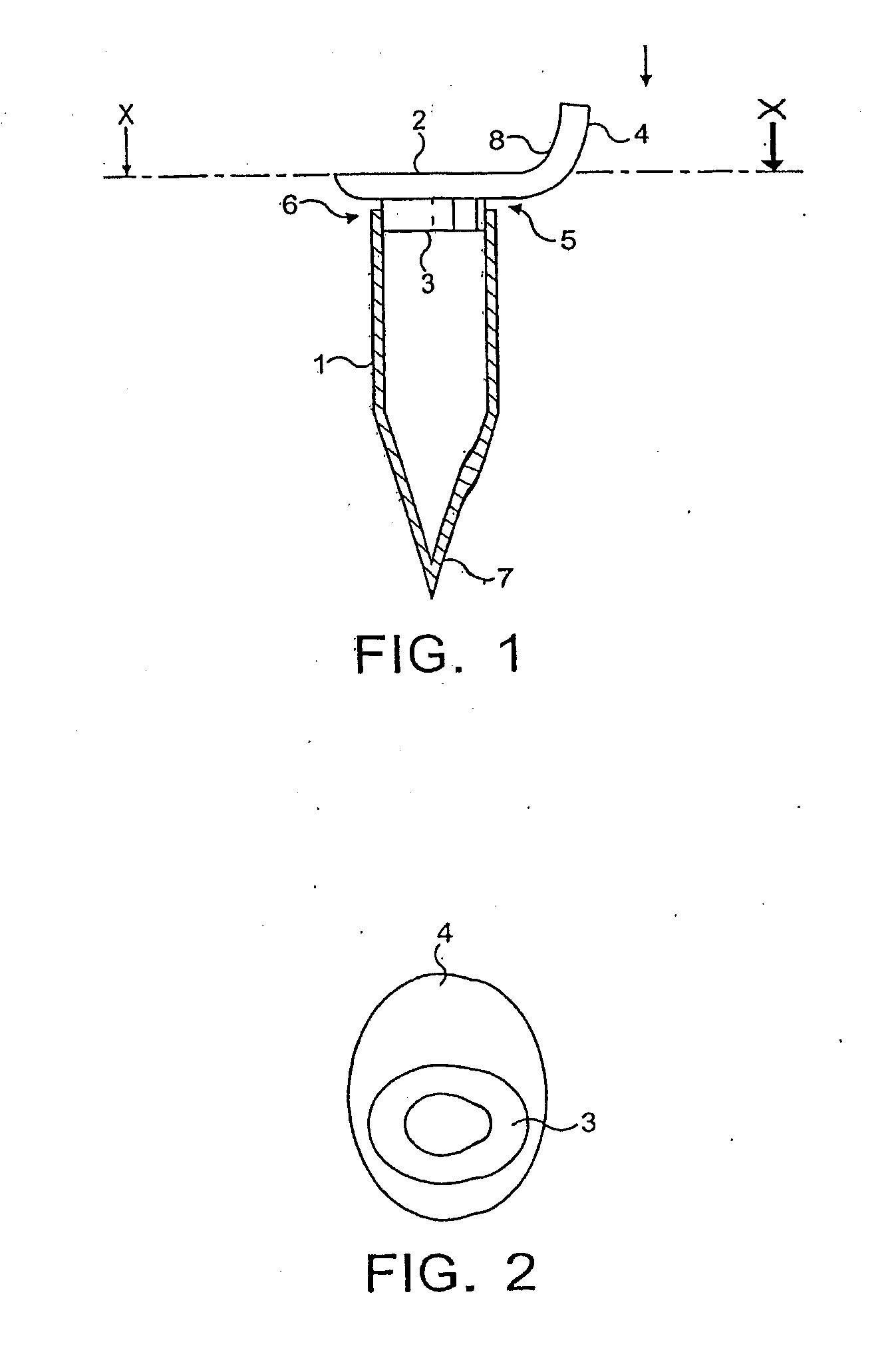
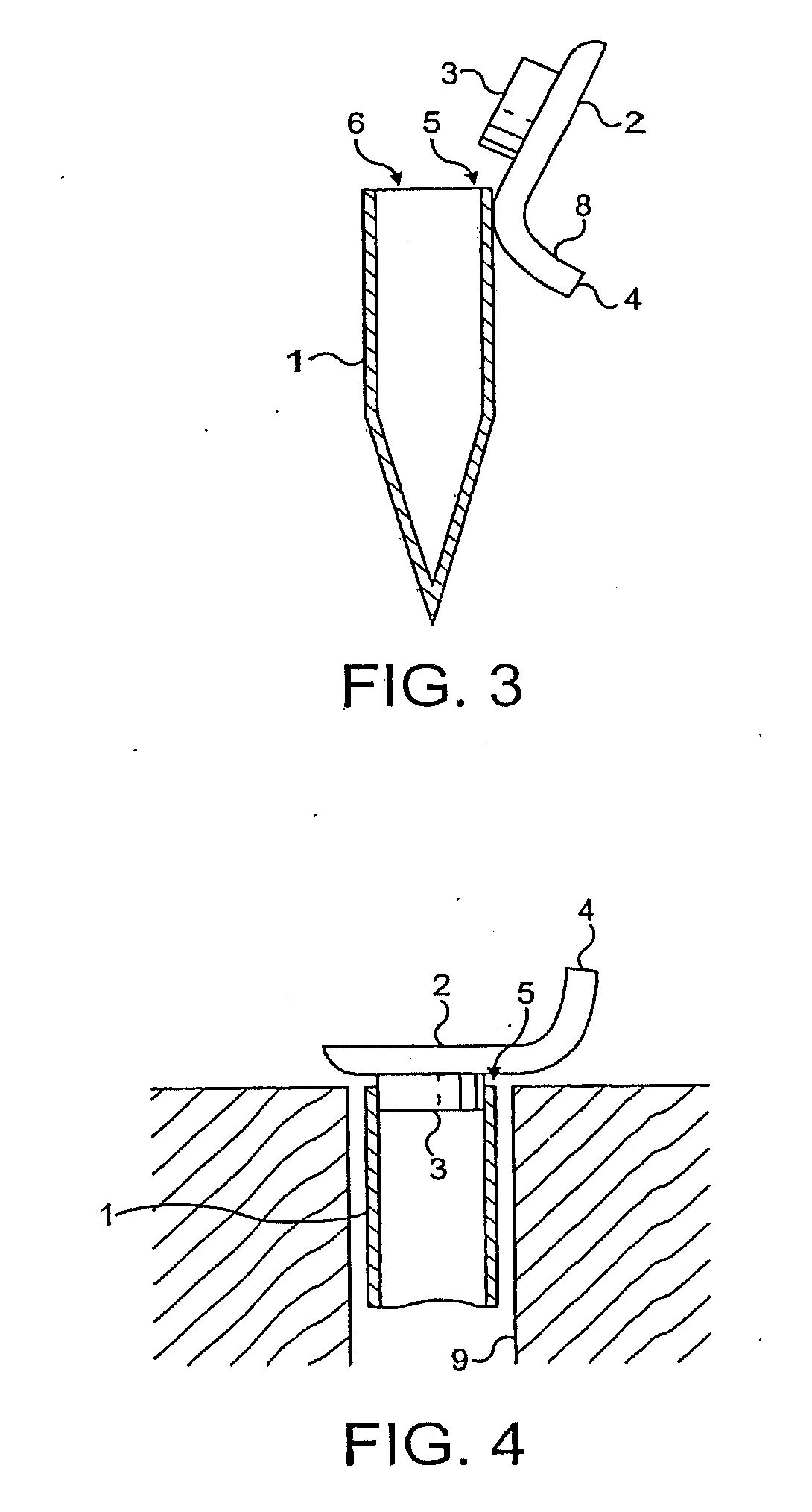
[0040]FIG. 1 of the accompanying drawings illustrates an embodiment of the microtube (1) according to the invention. The microtube (1) is approximately 4 cm in length and 1 cm in diameter, however the flange extends the diameter by up to 2 cm.

[0041]The tube (1) includes a container (7) having a circular opening (6) defined by an upper perimeter wall, for receiving materials to be contained in the tube. A lid (2) is connected to the perimeter wall of the opening (6) by a fixed hinge (5). The lower surface of the lid (3) makes sealing contact with the perimeter wall of the opening (6) thereby enclosing the contents of the container inside the tube.

[0042]The lid (2) has an upwardly and backwardly extending extension (4) that is integrally formed with the lid. The extension (4) extends from the lid (2) at a position adjacent to the hinge (5). Thumb pressure applied downwardly (in the direction of the arrow shown in FIG. 1) to the upper surface (8) of the extension (4) breaks the sealing...


PUM


Abstract

A novel microtube is provided comprising:a container having an open end defining an opening for receiving materials to be contained, and a closed end;a lid adapted to make closing contact with the opening of the container;wherein the lid is provided with a flange extending outwardly therefrom, and arranged to move towards the closed end of the container upon application of a mechanical force to a surface of the flange so as to remove the closing contact, whereby the container is opened.

Description

CROSS-REFERENCE TO RELATED APPLICATIONS[0001]This application is a continuation of U.S. patent application Ser. No. 10 / 525,127, filed Apr. 5, 2006, which is a national phase application under 35 U.S.C. §371 of International Application Number PCT / GB2003 / 003628 having an International Filing Date of Aug. 19, 2003, which claims the benefit of priority of GB Application No. 0219291.2, having a filing date of Aug. 19, 2002.BACKGROUND[0002]1. Field of the Invention[0003]The present invention relates to microtubes and further to apparatus, for example, centrifuges comprising microtubes according to the invention.[0004]2. Background Information[0005]Microtubes tend to comprise a container and separate screw tops, snap caps or attached caps. The screw top and snap cap require two hands to remove the tops. The attached caps must be pushed up with a thumb or forefinger, and also require two hands. One-handed operation can be attempted, however, in practice this is very difficult and often res...

Claims


Application Information

Patent Timeline
IPC IPC(8): B01L3/14B04B5/02
CPCB01L3/5021B01L2300/043B01L2300/042B01L3/50825
Inventor GARVIN, ROYBURNS, ALASDAIR
Owner MICROSTEIN LLC
Learn More