
Positionless Expanding Lock Ring For Subsea Annulus Seals For Lockdown

a technology of annulus seal and lockdown, which is applied in the direction of drilling casings, drilling pipes, borehole/well accessories, etc., can solve the problems of sealing leakage, sealing leakage, and increasing the manufacturing cost of the wellhead assembly, and achieve the effect of infinite adjustmen

Inactive Publication Date: 2012-09-27
VETCO GRAY
View PDF2 Cites 11 Cited by
  • Summary
  • Abstract
  • Description
  • Claims
  • Application Information

AI Technical Summary

Benefits of technology

"The present invention provides seal assemblies, wellhead assemblies, and methods of locking down an annulus seal positioned between an outer and inner wellhead members. The seal assembly includes an annulus seal member and an energizing member that can be activated to compress the seal and lock it in place. The seal assembly also includes a set of wickers that provide infinite adjustability within a certain window when setting the casing hanger and annulus seal. The lockdown ring is designed to plastically deform onto the wellhead housing and provide a secure lock. The seal assembly and wellhead assembly can provide improved load sharing and sealing performance."

Problems solved by technology

A reduction in axial force on the energizing ring results in a reduction in the radial inward and outward forces on the inner and outer walls of the seal ring, which may cause the seal to leak.
A loss of radial loading between the seal and its mating surfaces due to thermal transients may also cause the seal to leak.
Such annular groove may not only limit the axial positioning of the lockdown ring, resulting in increased manufacturing costs of the wellhead assembly, but may weaken or otherwise leave an area in the wellhead casing that is more vulnerable to stress, strain, thermal variations, etc.
; further increasing manufacturing costs directed to certain components of the wellhead assembly.
Additionally, recognized by the inventors is that such locking mechanisms that specifically must match a groove in a high-pressure wellhead housing may be subject to damage and debris fouling during the normal course of drilling operations.

Method used


Image

  • Positionless Expanding Lock Ring For Subsea Annulus Seals For Lockdown
  • Positionless Expanding Lock Ring For Subsea Annulus Seals For Lockdown
  • Positionless Expanding Lock Ring For Subsea Annulus Seals For Lockdown

Examples


Embodiment Construction

[0031]The present invention will now be described more fully hereinafter with reference to the accompanying drawings, which illustrate embodiments of the invention. This invention may, however, be embodied in many different forms and should not be construed as limited to the illustrated embodiments set forth herein. Rather, these embodiments are provided so that this disclosure will be thorough and complete, and will fully convey the scope of the invention to those skilled in the art. Like numbers refer to like elements throughout. Prime notation, if used, indicates similar elements in alternative embodiments.

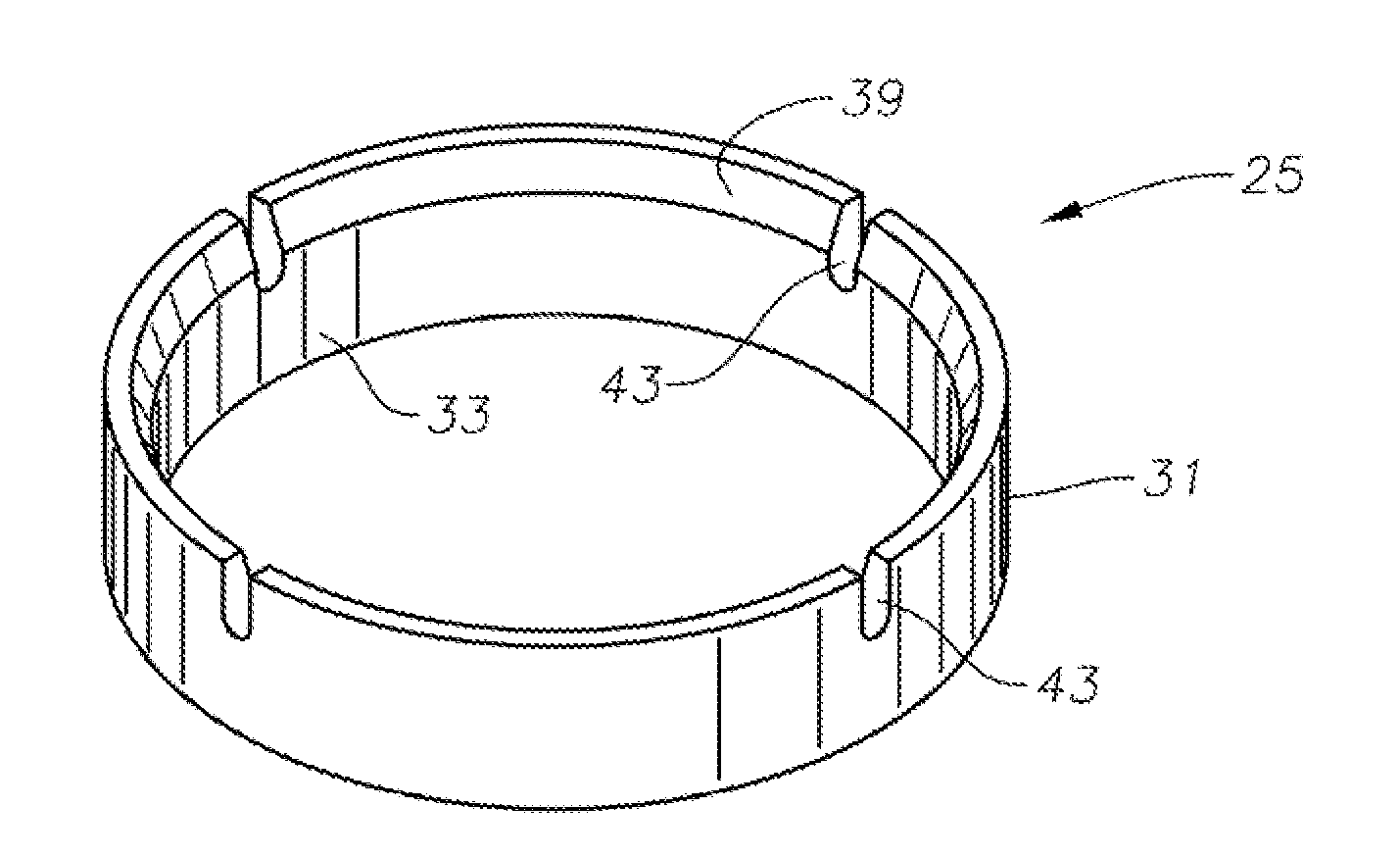
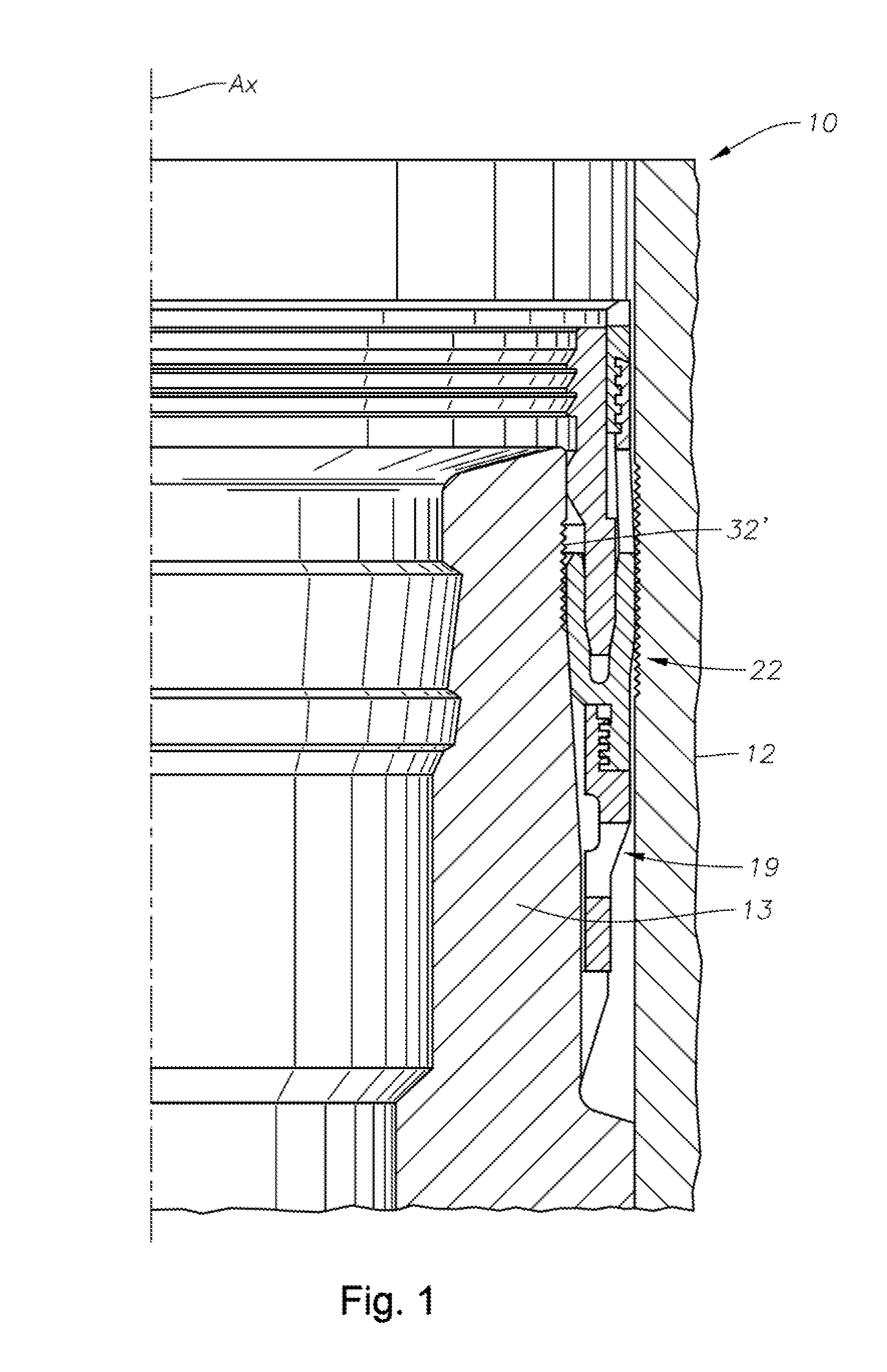
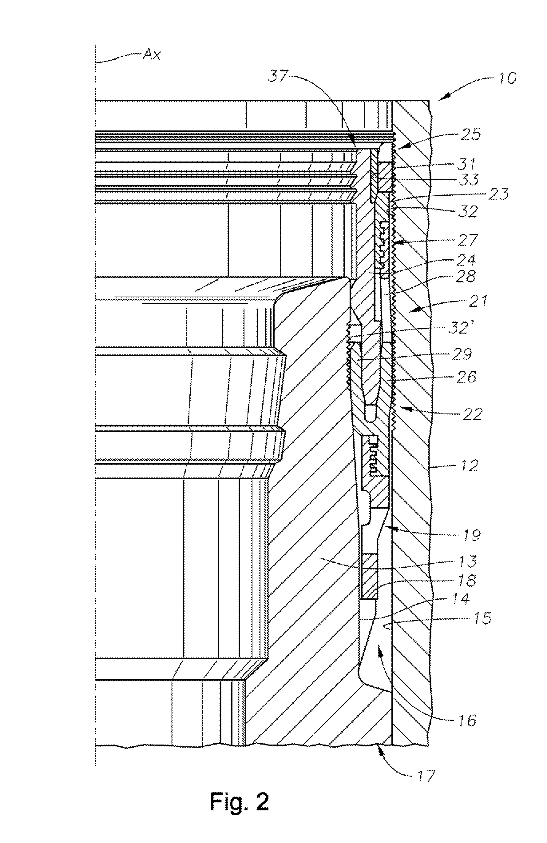
[0032]Existing annulus seals such as, for example, that shown in FIG. 1, may not provide enough lockdown capability during certain field conditions, particularly when employed in environmental conditions subject to significant swings in temperature and / or pressure. Lockdown force requirements come from annulus pressure and / or thermal growth of the casing string which then trans...


PUM


Abstract

Wellhead assemblies, seal assemblies, and methods of locking down an annulus seal disposed within an annulus between outer and inner wellhead members, are provided. A seal assembly is positioned in an annulus. An energizing member is axially translated downward to energize an annulus seal element and outwardly radially compress a high-strength lockdown member into contact with an inner diameter surface of a wellhead member. The wellhead member can include a set of wickers. During compression, the outer diameter surface of the lockdown member is plastically deformed onto the set of wickers.

Description

BACKGROUND OF THE INVENTION[0001]1. Field of the Invention[0002]This invention relates in general to wellhead assemblies and in particular to modified wellhead members and new seal assemblies for sealing between inner and outer wellhead members.[0003]2. Description of the Related Art[0004]Seals are used between inner and outer wellhead tubular members to contain internal well pressure. The inner wellhead member may be a casing hanger that supports a string of casing extending into the well for the flow of production fluid. The casing hanger lands in an outer wellhead member, which may be a wellhead housing, a Christmas tree, or a casing head. A packoff (or other seal assembly) seals the annulus between the casing hanger and the outer wellhead member. Alternately, the inner wellhead member can be a tubing hanger located in a wellhead housing and secured to a string of casing extending into the well. A pack off (or other seal assembly) seals the annulus between the tubing hanger and t...

Claims


Application Information

Patent Timeline
Patent Type & Authority Applications(United States)
IPC IPC(8): E21B33/12E21B33/03
CPCE21B33/03E21B33/04
Inventor GALLE, GARYMINASSIAN, MARC
Owner VETCO GRAY
Learn More