
Method and apparatus for synthesizing circular decompressors

a decompressor and circular technology, applied in the field of electronic design automation, can solve the problems of limiting the compression ratio of the most highly specified shift cycle, the encoded compression ratio of the combined decompressor, and the “unencodable” of the test cub

Active Publication Date: 2012-09-20
SYNOPSYS INC
View PDF4 Cites 19 Cited by
  • Summary
  • Abstract
  • Description
  • Claims
  • Application Information

AI Technical Summary

Benefits of technology

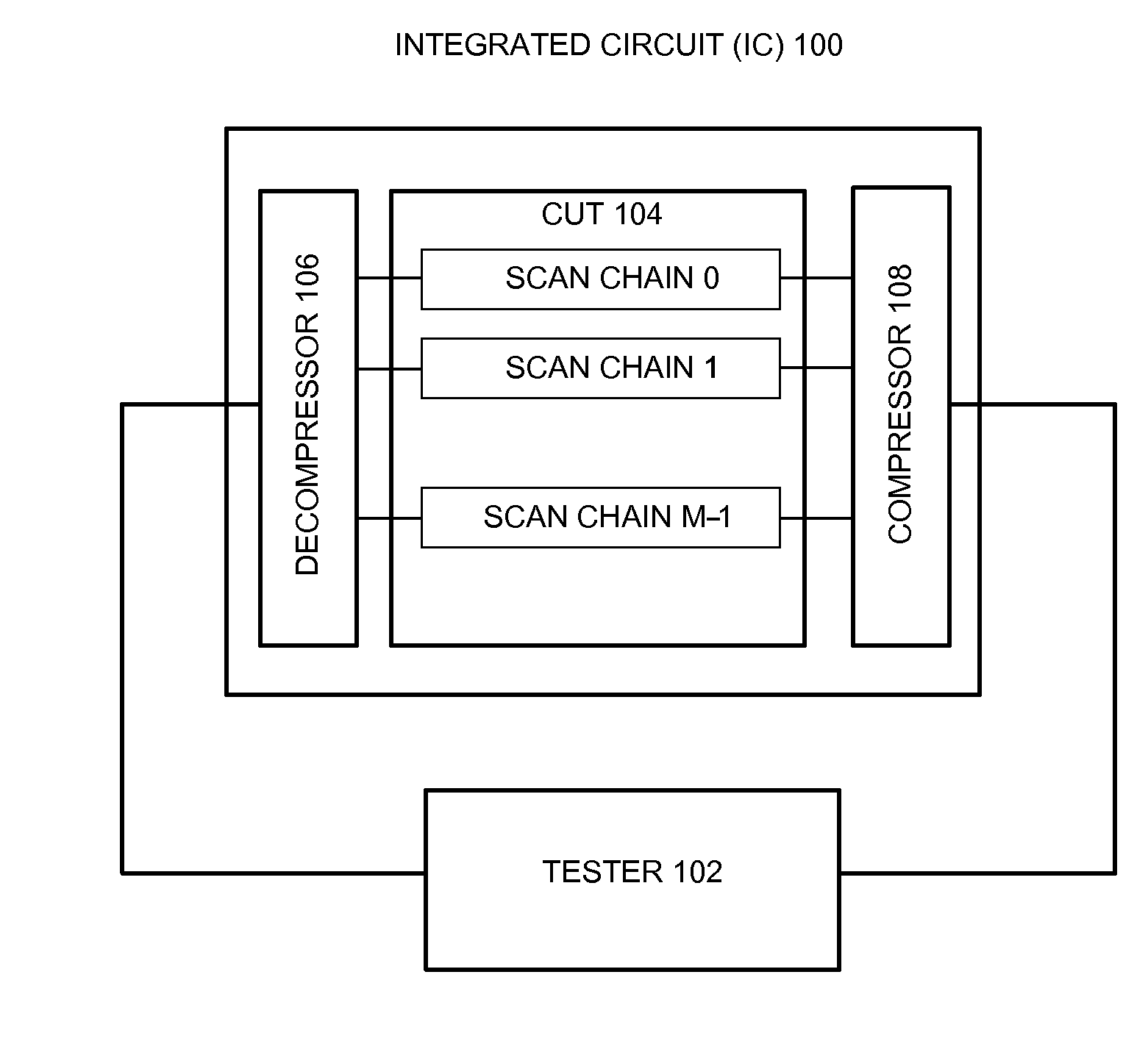
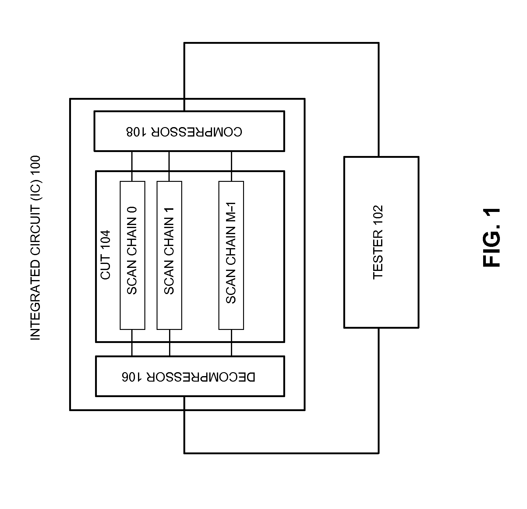
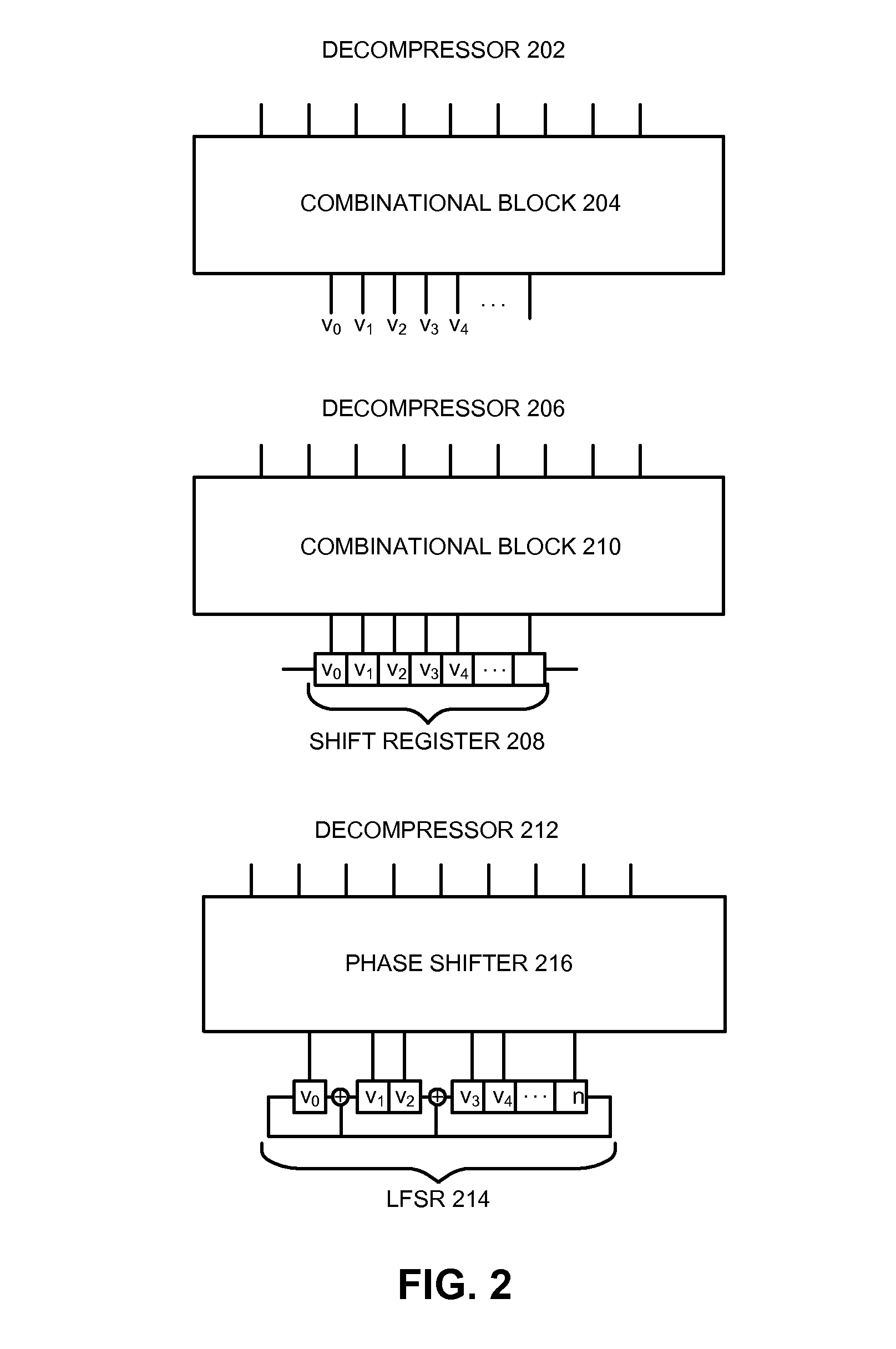
The patent describes an integrated circuit that can decompress test data from a tester and route the data to scan chains in a circuit under test. The circuit includes shift registers and logic networks to perform the decompression and routing functions. The shift registers have sequential elements that receive and shift the test data. The logic network includes XOR gates and a set of logic sequential elements to perform dynamic reseeding operations on the test data. The circuit can be controlled by a state of a control bit to determine which scan chain receives the test data. The test data can be divided into dynamic and static variables, and the circuit includes a set of shift registers to route the test data to the scan chains. The technical effects of the invention include improved test data decompression and routing capabilities, as well as improved accuracy and efficiency in testing complex circuits.

Problems solved by technology

However, the drawback of this scheme is that combinational decompressors have to encode all specified care bits in the test stimulus in one shift cycle using only test data bits (or variables) supplied from the tester for this shift cycle (typically comprising one test data bit for each tester channel).
This drawback can seriously limit the achievable compression ratio for the most highly specified shift cycles because the number of tester channels needs to be sufficiently large to encode the most highly specified shift cycles.
If no solution exists, then the test cube is considered “unencodable.” Note that it is difficult to encode a test cube that has more care bits than the number of available variables (or test data bits).
However, if the number of variables is sufficiently larger than the number of care bits in the test cube, the probability of not being able to encode the test cube becomes negligibly small.
On the other hand, the conventional sequential linear decompressor based on LFSRs or ring generators can imply very complex dependencies because each scan cell in the CUT can depend on the XOR of a large number of variables.
Incorporating such complex dependencies in the ATPG implication process can greatly increase the computational complexity of the ATPG.
As q increases, this computational complexity grows exponentially.
Because of this limitation, the conventional sequential linear decompressors do not fully utilize the degree of freedom in the ATPG.

Method used


Image

  • Method and apparatus for synthesizing circular decompressors
  • Method and apparatus for synthesizing circular decompressors
  • Method and apparatus for synthesizing circular decompressors

Examples


Embodiment Construction

[0059]The following description is presented to enable any person skilled in the art to make and use the embodiments, and is provided in the context of a particular application and its requirements. Various modifications to the disclosed embodiments will be readily apparent to those skilled in the art, and the general principles defined herein may be applied to other embodiments and applications without departing from the spirit and scope of the present disclosure. Thus, the present invention is not limited to the embodiments shown, but is to be accorded the widest scope consistent with the principles and features disclosed herein.

[0060]The data structures and code described in this detailed description are typically stored on a computer-readable storage medium, which may be any device or medium that can store code and / or data for use by a computer system. The computer-readable storage medium includes, but is not limited to, volatile memory, non-volatile memory, magnetic and optical...


PUM


Abstract

Methods and apparatuses are described for decompressing and routing test data. Some embodiments feature an integrated circuit (IC) that includes two or more shift registers configured to shift in the test data. Each of the two or more shift registers can include two or more sequential elements configured such that a scan chain in the set of scan chains receives inputs from at most one sequential element in each of the two or more shift registers. At least one shift register in the two or more shift registers can be configured as a circular shift register. The IC can also include a logic network coupled between the two or more shift registers and the set of scan chains such that the set of scan chains receives the decompressed test data from the two or more shift registers via the logic network.

Description

RELATED APPLICATION[0001]This application claims priority to U.S. Provisional Application No. 61 / 452,528, entitled “Method and Apparatus for Synthesizing Circular Decompressors,” by Emil I. Gizdarski, filed 14 Mar. 2011, the contents of which are herein incorporated by reference.BACKGROUND[0002]1. Technical Field[0003]This disclosure is generally related to electronic design automation in the integrated circuit industry. More specifically, this disclosure is related to techniques for testing integrated circuits and, in particular, for synthesizing decompressors for test stimulus decompression.[0004]2. Related Art[0005]Electronic design automation (EDA) is used by the semiconductor industry for virtually all integrated circuit (IC) design projects. More specifically, after developing a product idea, EDA tools are used to define a specific implementation. The implementation defined using the EDA tools is then used to create mask data, which is subsequently used for producing masks in ...

Claims


Application Information

Patent Timeline
Patent Type & Authority Applications(United States)
IPC IPC(8): G01R31/3177G06F11/25
CPCG01R31/318547G01R31/318544G01R31/318335
Inventor GIZDARSKI, EMIL I.
Owner SYNOPSYS INC
Learn More