
Backlight assembly and display apparatus having the same

a backlight assembly and display apparatus technology, applied in lighting and heating apparatus, planar/plate-like light guides, instruments, etc., to achieve the effect of effectively providing to a display panel, reducing the thickness of the display apparatus, and reducing the size of the bezel of the display apparatus

Active Publication Date: 2012-09-20
SAMSUNG DISPLAY CO LTD
View PDF6 Cites 8 Cited by
  • Summary
  • Abstract
  • Description
  • Claims
  • Application Information

AI Technical Summary

Benefits of technology

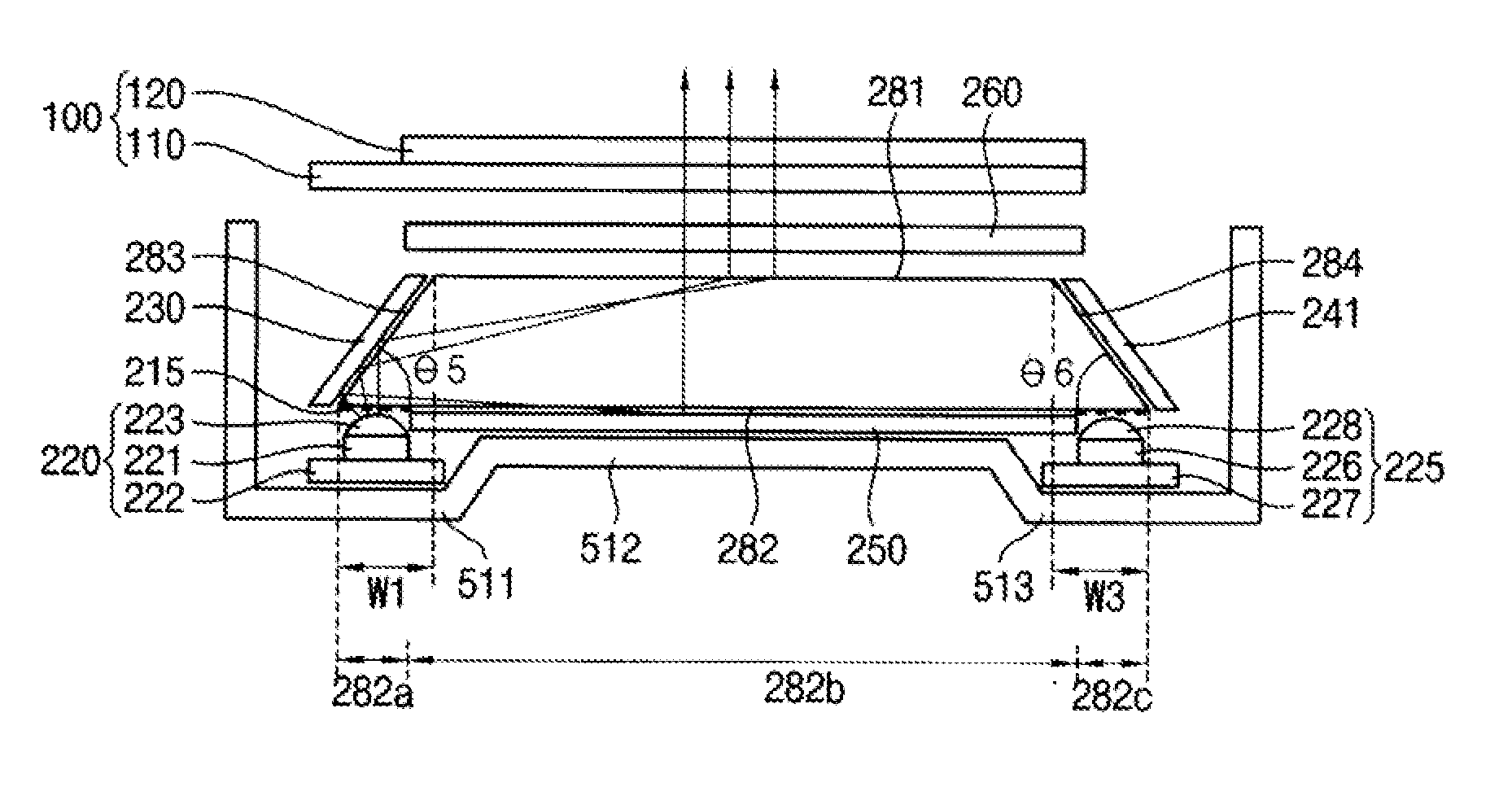
The present invention provides a backlight assembly and display apparatus with reduced thickness and size, while still efficiently supplying light. The backlight assembly includes a light guiding plate and first light sources, which are disposed under the light guiding plate and adjacent to its edges. The light guiding plate has a first surface with a light exiting surface and a light guiding surface opposite to the light exiting surface, with a first angle between them. The first light sources are positioned under the light guiding plate and adjacent to the first edge of the light guiding plate. The backlight assembly also includes a first reflecting cover and a second reflecting cover, which are disposed on the light guiding surface and positioned to correspond to the incident portion and reflect the light. The display apparatus includes a display panel and the backlight assembly for displaying an image using the light. The technical effects of the invention include reduced thickness and size of the backlight assembly and display apparatus, efficient supply of light, and improved image quality.

Problems solved by technology

This can be an impediment to reducing the thickness of display apparatuses that include an edge-illumination type backlight assembly.

Method used


Image

  • Backlight assembly and display apparatus having the same
  • Backlight assembly and display apparatus having the same
  • Backlight assembly and display apparatus having the same

Examples


Embodiment Construction

[0043]Hereinafter, the present invention will be explained in detail with reference to the accompanying drawings.

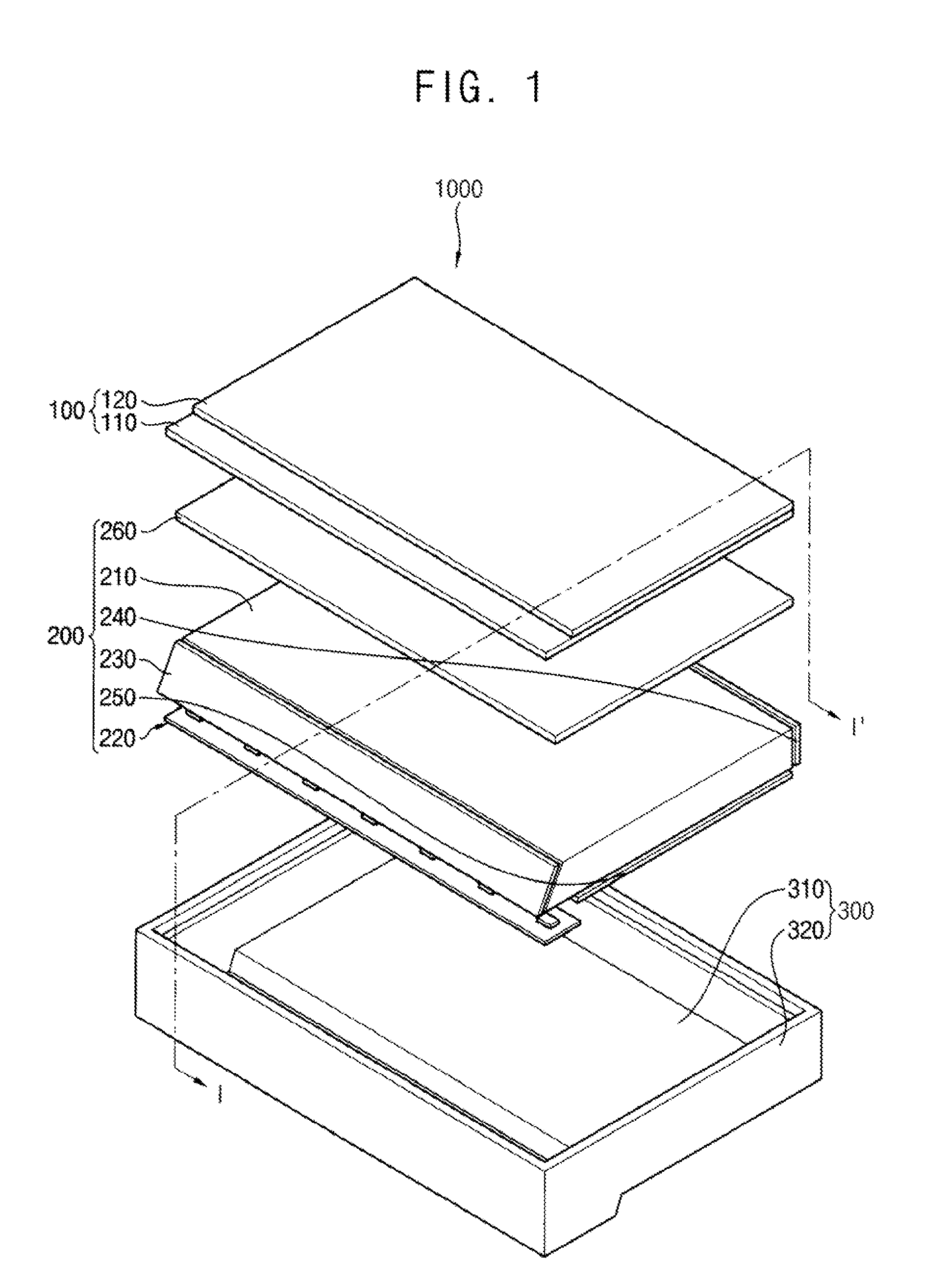
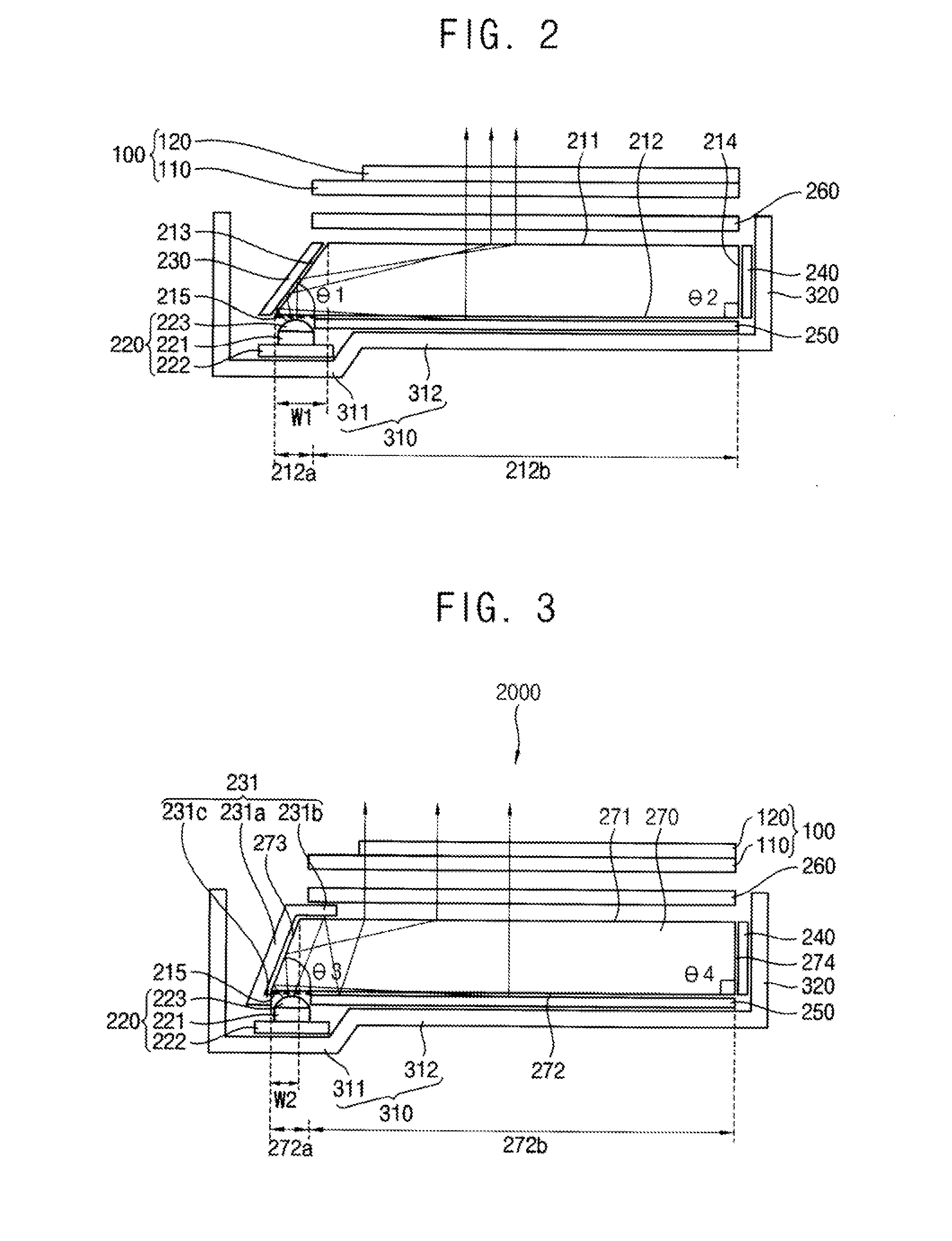
[0044]FIG. 1 is an exploded perspective view illustrating a display apparatus according to an example embodiment of the present invention. FIG. 2 is a cross-sectional view taken along line I-I′ of FIG. 1.

[0045]Referring to FIGS. 1 and 2, a display apparatus 1000 includes a display panel 100, a backlight assembly 200 and a receiving container 300.

[0046]The display panel 100 includes a first substrate 110, a second substrate 120 facing the first substrate 110, and a liquid crystal layer (not shown) disposed between the first and second substrates 110 and 120. An image is displayed from the display panel 100, using light from the backlight assembly 200.

[0047]The backlight assembly 200 includes a light guiding plate 210, a light source 220, a first reflecting cover 230, a second reflecting cover 240, a reflecting sheet 250 and a light controller 260.

[0048]The light guiding pl...


PUM


Abstract

A backlight assembly includes a light guiding plate and a plurality of first light sources. The light guiding plate includes a light exiting surface through which light can exit, a light guiding surface positioned opposite to the light exiting surface, and a first surface extending between the light guiding surface and the light exiting surface and inclined with respect to the light guiding surface by a first angle. The first angle is an acute angle. The first light sources can generate light, and are disposed under the light guiding plate. These first light sources are disposed adjacent to a first edge connecting the first surface with the light guiding surface.

Description

CROSS-REFERENCE TO RELATED APPLICATION[0001]This application claims priority under 35 U.S.C. §119 to Korean Patent Application No. 2011-0023464, filed on Mar. 16, 2011, in the Korean Intellectual Property Office (KIPO), the contents of which are herein incorporated by reference in their entireties.BACKGROUND OF THE INVENTION[0002]1. Field of the Invention[0003]Example embodiments of the present invention relate generally to flat panel displays. More particularly, example embodiments of the present invention relate to a backlight assembly for a flat panel display, the backlight assembly having a light guiding plate, as well as a display apparatus having the backlight assembly.[0004]2. Discussion of the Related Art[0005]Generally, a display apparatus includes a display panel and a backlight assembly supplying light to the display panel. The backlight assembly is classified into an edge-illumination type and a direct-illumination type according to a position of a light source. The edge...

Claims


Application Information

Patent Timeline
Patent Type & Authority Applications(United States)
IPC IPC(8): F21V7/04F21V29/00
CPCG02B6/0016G02B6/0055G02B6/0018G02B26/02G02F1/133524G02F1/1336G02F1/133615G02F1/133628
Inventor SHIN, DONG-LYOULCHOI, JAE-CHANGLEE, TAE-HOYOO, JE-WONRYU, SU-CHANG
Owner SAMSUNG DISPLAY CO LTD
Learn More