Destructive web thickness measuring system of microdrills and method thereof

Inactive Publication Date: 2012-09-20
CHANG WEN TUNG +4
View PDF1 Cites 6 Cited by
  • Summary
  • Abstract
  • Description
  • Claims
  • Application Information

AI Technical Summary

Benefits of technology

[0008]The destructive web thickness measuring system of microdrills and the destructive web thickness measuring method of microdrills according to the present invention can be used for automatically measuring the web thickness value of the microdrill at the sectional position to be inspected. By the design of the positioning vision module, it can be effective to ensure whether the drill grinding module grinds the microdrill to the sectional position to be inspected in the positioning procedure and the grinding procedure. By the design of the web thickness measuring vision module and the image computing procedure, the measuring stability of the destructive web thickness measuring system of microdrills according to the present invention can be improved. By the setting of the computer device, the process of the destructive web thickness measurement of the microdrill can be effectively controlled.

Problems solved by technology

The microdrill 50 with a greater web thickness 62 can lead to good drill rigidity while the depth of the helical flute 58 is smaller, thus resulting in a poor chip-removing effect.
However, in practice, the non-destructive measuring technology for the web thickness value still has problems such as a high cost and insufficient stability, which fails to facilitate the development of the non-destructive measuring technology for the web thickness value.
In view of the above problems, industries in the art still adopt a destructive measuring technology for the web thickness value.
Since the above process is manually operated, the problems that it requires long time and it is difficult to ensure accuracy of an inspected position and precision of a web thickness value exist.

Method used


Image

  • Destructive web thickness measuring system of microdrills and method thereof
  • Destructive web thickness measuring system of microdrills and method thereof
  • Destructive web thickness measuring system of microdrills and method thereof

Examples


Embodiment Construction

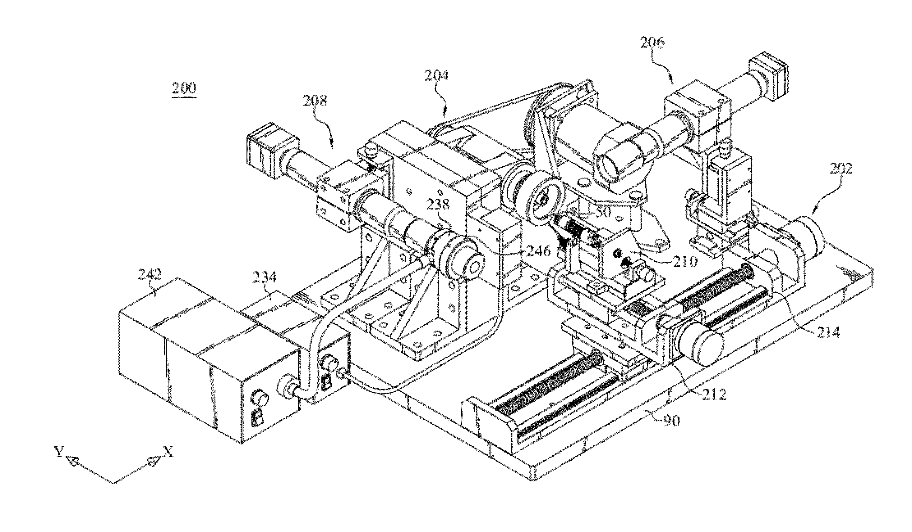
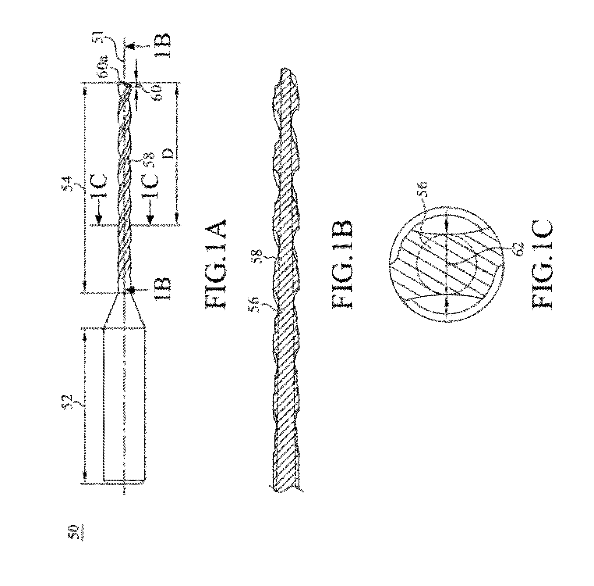
[0028]FIGS. 2A, 2B, and 2C are respectively a schematic structural block diagram of a destructive web thickness measuring system of microdrills according to an embodiment of the present invention, a three-dimensional schematic structural view and a top schematic structural view of a dual-axis motion platform module, a drill grinding module, a positioning vision module, and a web thickness measuring vision module according to an embodiment of the present invention. In this embodiment, a destructive web thickness measuring system of microdrills 200 is suitable for measuring a web thickness 62 of a microdrill 50 at a sectional position to be inspected D (referring to FIGS. 1A and 1C). The destructive web thickness measuring system of microdrills 200 comprises a computer device 201, a dual-axis motion platform module 202, a drill grinding module 204, a positioning vision module 206, a web thickness measuring vision module 208, a grinding wheel switch submodule 248, and a motion control ...


PUM


Abstract

A destructive web thickness measuring system of microdrills includes a computer device, a dual-axis motion platform module, a drill grinding module, a positioning vision module, and a web thickness measuring vision module. When the computer device controls the dual-axis motion platform module to move a microdrill to a first locating position, the computer device performs a positioning procedure according to a first image captured by the positioning vision module, and then performs a grinding procedure, so that the drill grinding module grinds the microdrill to a sectional position to be inspected. When the ground microdrill moves to an image measuring position, the computer device performs an image computing procedure according to a second image captured by the web thickness measuring vision module, so as to obtain a web thickness value. Therefore, the destructive web thickness measuring system of microdrills can automatically measure the web thickness value.

Description

FIELD OF INVENTION[0001]The present invention relates to a destructive web thickness measuring system of microdrills and a method thereof, and more particularly to an automated destructive web thickness measuring system of microdrills and a method thereof.RELATED ART[0002]Microdrills have been widely applied in microhole drilling of various printed circuit boards. FIGS. 1A, 1B, and 1C are respectively a side schematic structural view of a microdrill according to an embodiment, a schematic structural view of a radial section 1B-1B according to FIG. 1A, and a schematic view of an axial section 1C-1C according to FIG. 1A. A microdrill 50 includes a central axis 51, a shank 52, and a drill body 54, wherein the drill body 54 includes a drill point 60, a helical flute 58, and a drill tip 60a. The drill body 54 is magnified in scale relative to the shank 52 for ease of illustration. The drill body 54 is composed of the drill point 60 and the helical flute 58 in function. The drill point 60...

Claims


Application Information

Patent Timeline
IPC IPC(8): H04N7/18
CPCG01B11/02G01B11/24G01B11/06
Inventor CHANG, WEN-TUNGCHUANG, SHUI-FATSAI, YI-SHANTANG, GEO-RYSHIOU, FANG-JUNG
Owner CHANG WEN TUNG
Why Eureka
Try Eureka