Safety lamp

a safety lamp and lamp body technology, applied in the field of safety lamps, can solve the problems of short life span, high power consumption, electric shock for users when installing or removing lamps, etc., and achieve the effect of high safety of lamp installmen

Inactive Publication Date: 2012-09-20
ADVANCED CONNECTEK INC
View PDF3 Cites 6 Cited by
  • Summary
  • Abstract
  • Description
  • Claims
  • Application Information

AI Technical Summary

Benefits of technology

[0005]An objective of the present invention is to provide a safety lamp to achieve safety in installing and removing the lamp without requiring the consumers to change the accustomed procedures of installing and removing the lamp.
[0006]Another objective of the present invention is to provide a safety lamp that can be used safely without changing the design of the current lamp holders.
[0007]A further objective of the present invention is to provide a safety lamp in which safety can be highly achieved by a simple elastic switch mechanism with low cost.
[0008]Another objective of the present invention is to provide a safety lamp, which has two pressing switch units on both sides, and the safety lamp is electrically connected to the lamp holder only when both pressing switch units are pressed. Therefore, when a user installs or removes the safety lamp and one side of the safety lamp is electrically connected to the lamp holder, the pressing switch unit on the other side of the safety lamp is free from pressing and an open circuit is formed, so the user is free from being exposed to the danger of electric shock by touching the electrode pins on the side where the pressing switch unit is free from pressing, and the high safety is thus achieved.
[0010]Comparing to the conventional technology, the safety lamp of the present invention is provided to be electrically connected via the elastic conductive unit by selection of the pressing switch unit when a user to install the safety lamp, thus avoiding the possibility that the user is exposed to the electric shock in installing the lamp to the lamp holder and achieving high safety of lamp installment. When the safety lamp is installed to the lamp holder, both pressing switch units of the two electric connecting portions on the two side of the safety lamp must be installed and pressed in the lamp holder to form a closed circuit between the safety lamp and the lamp holder.

Problems solved by technology

Conventional fluorescent lamps are known for their advantages to have wide light emission areas, but also have major drawbacks such as high power consumption and short life spans.
However, when a user installs or removes a lamp, and the electrode pins on one side of the lamp is electrically connected to the power slots, it is possible that the user would touch the electrode pins exposed on the other side of the lamp to form a closed circuit, as shown in FIG. 1, thus creating danger of electric shock for the user in installing or removing the lamp.

Method used


Image

  • Safety lamp
  • Safety lamp
  • Safety lamp

Examples


Embodiment Construction

[0018]The techniques employed by the present invention to achieve the foregoing objectives, characteristics and effects thereof are described hereinafter by way of examples with reference to the accompanying drawings.

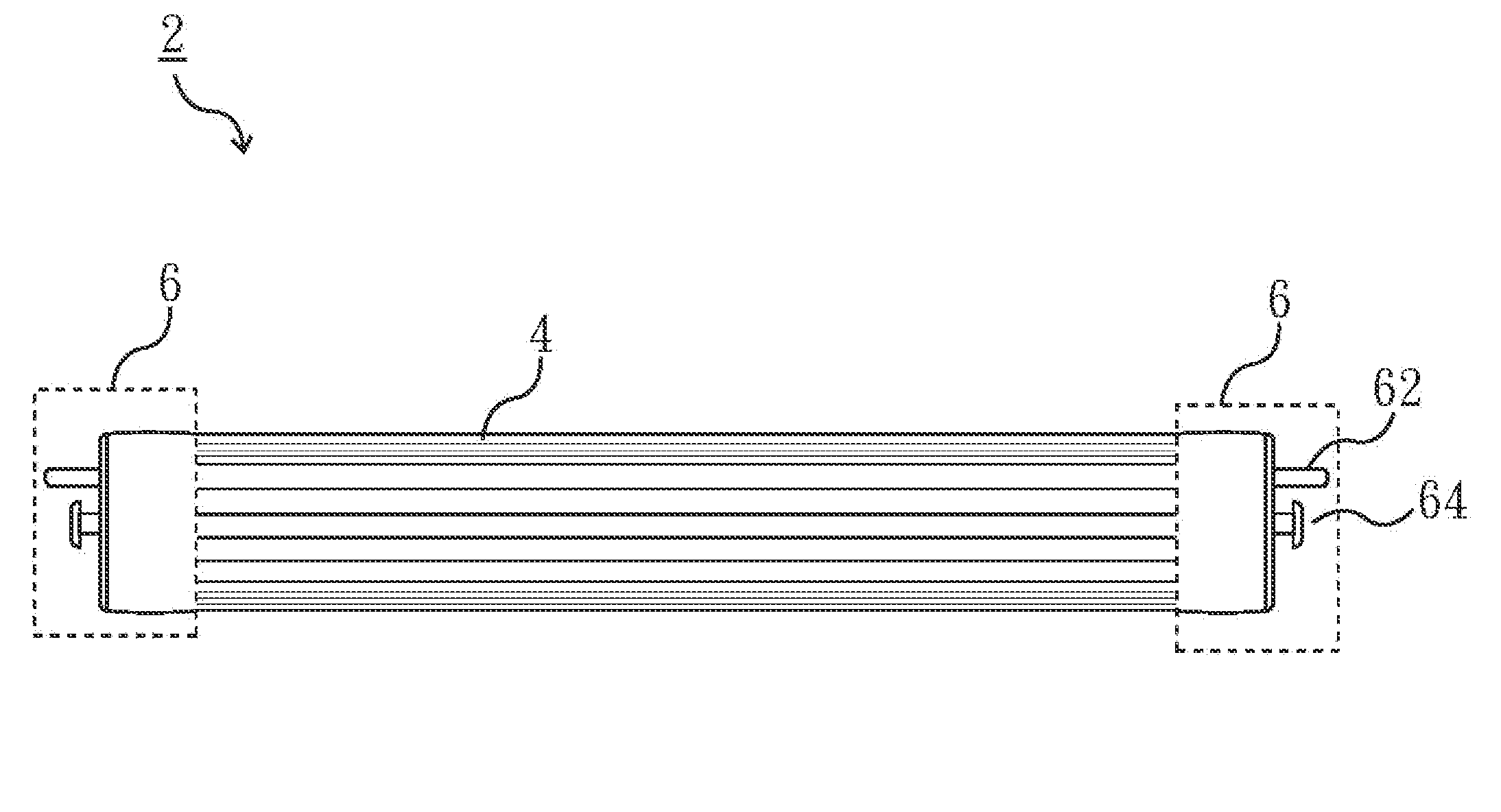
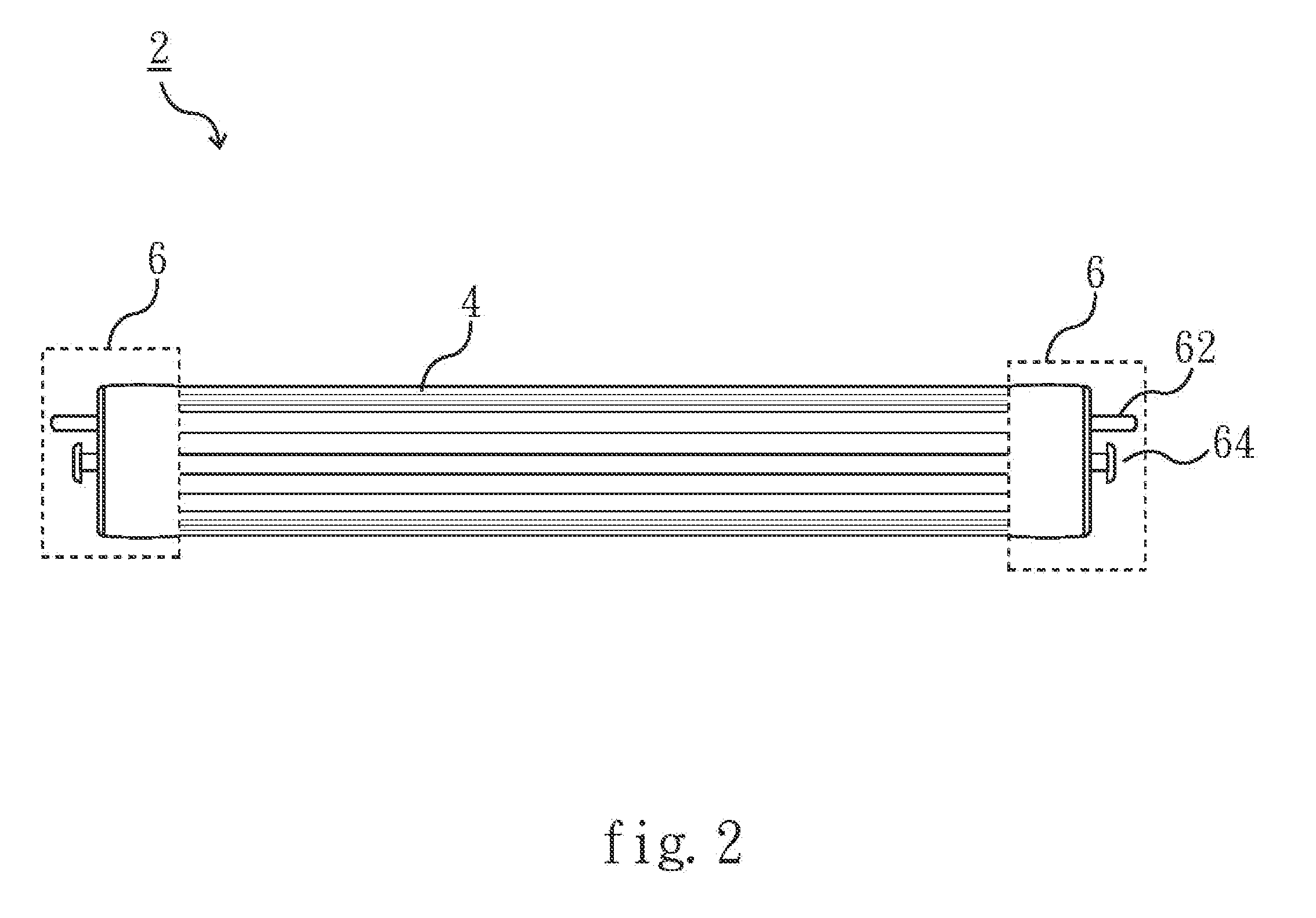
[0019]Referring to FIG. 2 and FIG. 3, FIG. 2 is a schematic view of an embodiment of a safety lamp of the present invention, and FIG. 3 is a schematic view of another embodiment of a safety lamp of the present invention. In the figures, the safety lamp 2 comprises a lamp body 4 and two electric connecting portions 6. The lamp body 4 has a light emitting module, and the light emitting module can be an organic light emitting diode (OLED) module, a light emitting diode (LED) module, or an electroluminescent (EL) module. Each of the two electric connecting portions 6 is respectively disposed on two sides of the lamp body 4, and each has a first electric connecting terminal 62 and a pressing switch unit 64 at its outside. It should be noted that the first electric connecting...


PUM


Abstract

A safety lamp, which comprises a lamp body and two electric connecting portions. The lamp body has a light emitting module. The two electric connecting portions are respectively disposed on two sides of the lamp body, and each of the electric connecting portions further comprises a first electric connecting terminal, a pressing switch unit, an elastic conductive unit and a second electric connecting terminal. Each of the pressing switch units must sustain a pressing force to urge against the corresponding elastic conductive unit to deform and to electrically connect the corresponding first electric connecting terminal to the corresponding second electric connecting terminal through the elastic conductive unit. Alternatively, when the pressing switch unit is released from the pressing force, the deformed elastic conductive unit reforms back to an opposite direction of the pressing force to form an open circuit.

Description

FIELD OF THE INVENTION[0001]The present invention relates to a safety lamp, and particularly to a safety lamp having a pressing switch unit for a user to install the safety lamp without being exposed to danger of electric shock.BACKGROUND[0002]Conventional fluorescent lamps are known for their advantages to have wide light emission areas, but also have major drawbacks such as high power consumption and short life spans. In recent years, with improvement of light emission technology, lamps such as light emitting diodes (LEDs), organic light emitting diodes (OLEDs), and electroluminescent (EL) lamps are introduced. These new lamps have longer life spans and lower power consumption and generate less heat. However, to fit in the lamp holders of the current lamps, the new lamps are designed to have a plurality of electrode pins on their sides such that the electrode pins can be electrically connected to the power slots of the lamp holders to provide electricity power to the lamps.[0003]H...

Claims


Application Information

Patent Timeline
Patent Type & Authority Applications(United States)
IPC IPC(8): H01J1/62H01J5/00
CPCF21V19/04F21V23/04F21V25/04F21K9/175H01R33/08H01R33/96F21Y2101/02F21K9/272F21Y2115/10F21V19/00
Inventor WU, YU-CHI
Owner ADVANCED CONNECTEK INC
Why Eureka
Try Eureka