
Assembly for electrical breakdown protection for high current, non-elongate solar cells with electrically conductive substrates

a solar cell and substrate technology, applied in the direction of electrical equipment, semiconductor/solid-state device manufacturing, semiconductor devices, etc., can solve the problems of high cost associated with traditional diode devices being appropriately packaged for use in the solar industry, affecting and reducing the cost of the device. , to achieve the effect of improving the long-term reliability of the module and excellent heat sink properties

Inactive Publication Date: 2012-09-20
AERIS CAPITAL SUSTAINABLE IP
View PDF4 Cites 37 Cited by
  • Summary
  • Abstract
  • Description
  • Claims
  • Application Information

AI Technical Summary

Benefits of technology

[0007]Optionally, the device comprises a non-elongated, non-silicon thin-film solar cell using an electrically conductive foil substrate wherein the foil substrate carries current when the cell is forward biased, the substrate having a ratio of width to length greater than about 0.5 along an axis of current flow, and when exposed to light at AM 1.5G, the solar cell has an Impp greater than about 4 amps; an avalanche breakdown protection assembly to prevent the avalanche breakdown at the one or more locations by directing current through the protection unit.
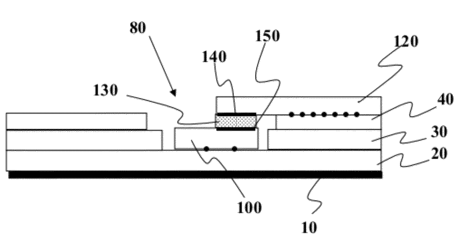
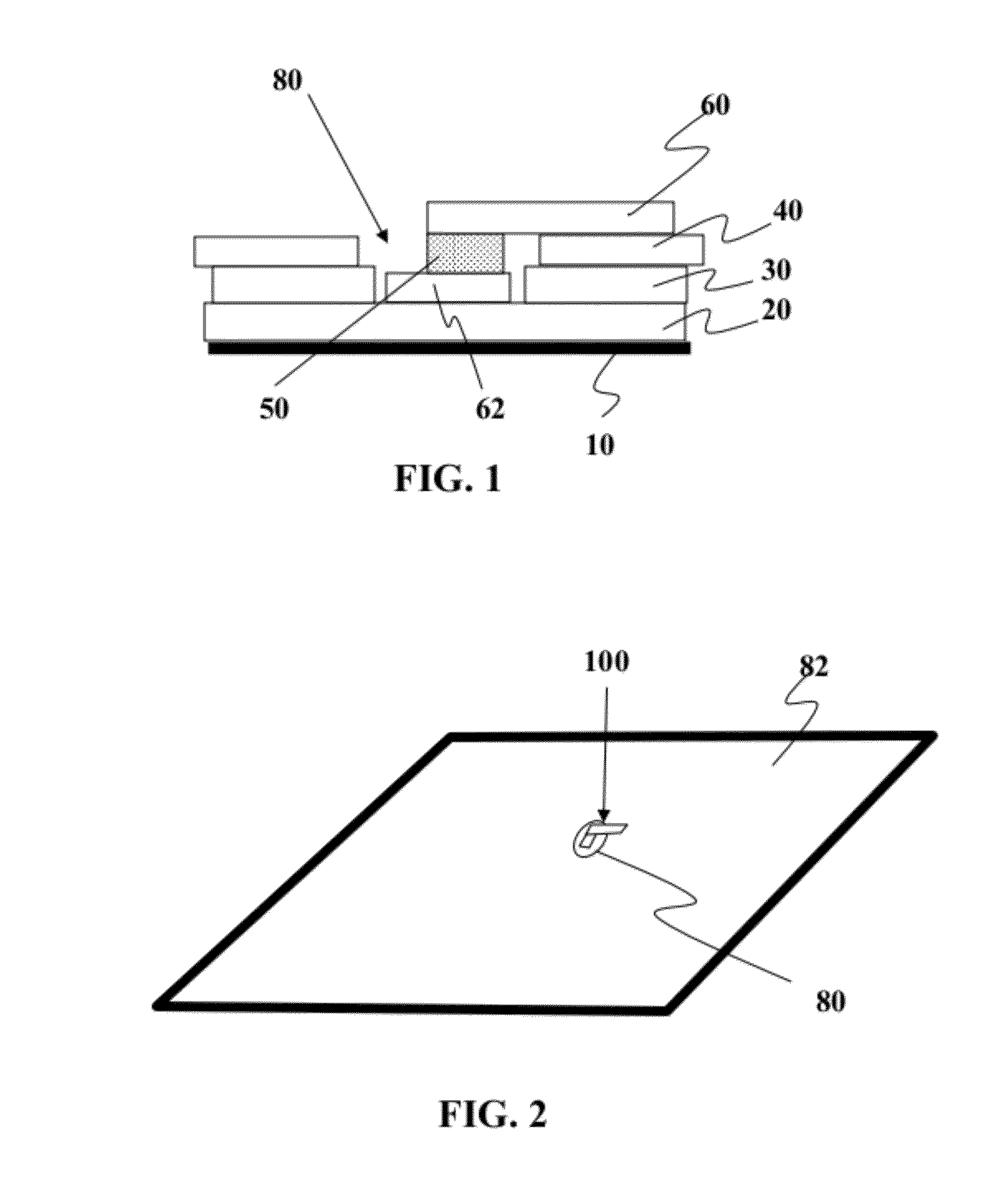
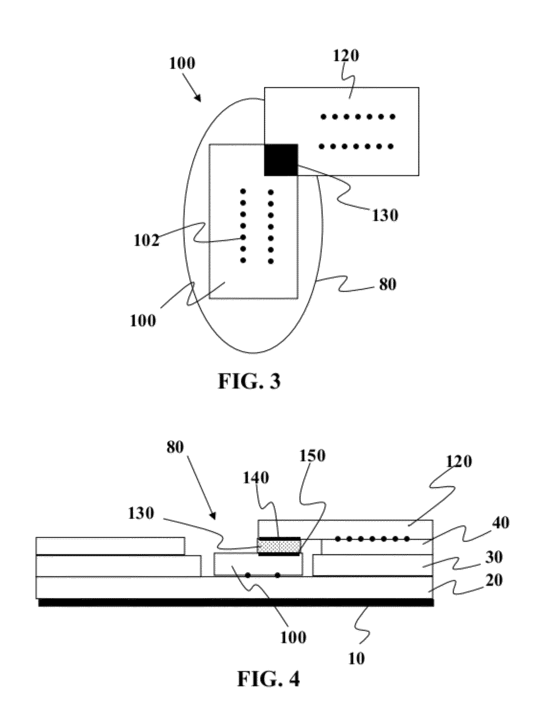
[0021]In one embodiment, the present invention, due to its use of a flexible structure that utilizes solar cells that are made on a metallic foil substrate, allows use of the metallic foil substrate as the heat sink for the bypass diodes. Thus, bypass diodes placed over the back surface of the metallic substrates of the solar cells may be thermally coupled to the solar cell substrates and any heat generated by the bypass diode can easily be dissipated to the large area solar cell and eventually to outside of the module. This also allows usage of bypass diodes that are sized to correspond to the module current rating, or some small percentage greater than the module current rating for reliability reasons, such as 10% or 20% larger. It should be noted that the typical size of the solar cells made on flexible substrates as described herein are larger than about 100 cm.sup.2, whereas the typical size of the bypass diodes that correspond to the module current rating is less than 1 cm.sup.2. Therefore, the cell provides excellent heat sink properties to the bypass diode. This increases the long term reliability of the module.

Problems solved by technology

A central challenge in cost-effectively providing breakdown protection in a photovoltaic device relates in part to the assembly processes used for photovoltaic cell manufacturing and the high cost associated with traditional diode devices being appropriately packaged for use in the solar industry.
The size of the traditional packaging of diodes or other protection devices make them cumbersome to incorporate into the module at the cell level, and furthermore, such packaging introduces a variety of complexities for integrating such protection devices into traditional solar cells.
However, even with these cells, some issues remain that may be addressed by having breakdown protection.

Method used


Image

  • Assembly for electrical breakdown protection for high current, non-elongate solar cells with electrically conductive substrates
  • Assembly for electrical breakdown protection for high current, non-elongate solar cells with electrically conductive substrates
  • Assembly for electrical breakdown protection for high current, non-elongate solar cells with electrically conductive substrates

Examples


Embodiment Construction

[0036]It is to be understood that both the foregoing general description and the following detailed description are exemplary and explanatory only and are not restrictive of the invention, as claimed. It may be noted that, as used in the specification and the appended claims, the singular forms “a”, “an” and “the” include plural referents unless the context clearly dictates otherwise. Thus, for example, reference to “a material” may include mixtures of materials, reference to “a compound” may include multiple compounds, and the like. References cited herein are hereby incorporated by reference in their entirety, except to the extent that they conflict with teachings explicitly set forth in this specification.

[0037]In this specification and in the claims which follow, reference will be made to a number of terms which shall be defined to have the following meanings:

[0038]“Optional” or “optionally” means that the subsequently described circumstance may or may not occur, so that the des...


PUM


Abstract

Methods and devices are provided for avalanche breakdown in a thin-film solar cell. In one embodiment, a method of breakdown protection assembly comprises providing a single reel of material which is pre-cut in a pattern so that a first portion of the material can be overlapped to a second portion of material to sandwich a breakdown protection device therebetween

Description

FIELD OF THE INVENTION[0001]This invention relates to using a photovoltaic device with electrical breakdown protection.BACKGROUND OF THE INVENTION[0002]A central challenge in cost-effectively providing breakdown protection in a photovoltaic device relates in part to the assembly processes used for photovoltaic cell manufacturing and the high cost associated with traditional diode devices being appropriately packaged for use in the solar industry. The size of the traditional packaging of diodes or other protection devices make them cumbersome to incorporate into the module at the cell level, and furthermore, such packaging introduces a variety of complexities for integrating such protection devices into traditional solar cells.[0003]Furthermore, thin-film solar cells such as those comprised of CIGS or other IB-IIIA-VIA material have often not needed diodes as these cells when made on metal foil and were able to withstand hot spots without comprising the entire module. However, even w...

Claims


Application Information

Patent Timeline
IPC IPC(8): H01L31/02H01L31/024H01L31/18
CPCH01L31/0504H01L31/0443H01L31/046Y02E10/50H01L31/0465
Inventor STANCEL, ROBERTJALBERT, JOSEPH
Owner AERIS CAPITAL SUSTAINABLE IP
Learn More