
Elastically stretchable fabric force sensor arrays and methods of making

a technology of elastic stretch and fabric, applied in the field of transducers or sensors, can solve the problems of affecting tissue damage, causing damage to internal tissues, and generating damagingly large shear stresses, etc., to achieve the effect of limiting the stretch and enhancing the stretchability and conformability of the sensor array according to the present invention

Active Publication Date: 2012-09-20
PATIENTECH LLC
View PDF3 Cites 52 Cited by
  • Summary
  • Abstract
  • Description
  • Claims
  • Application Information

AI Technical Summary

Benefits of technology

[0018]An object of the present invention is to provide elastically stretchable arrays of force or pressure sensing transducers which are conformable to objects having complex, compoundly curved shapes such as human body parts, to facilitate measuring and mapping forces or pressures exerted on such objects.

Problems solved by technology

The forces exerted on body parts by support surfaces, which are equal and opposite to body weight forces, can in some cases cause damage to tissues.
High pressure alone is generally not sufficient to deleteriously affect tissue.
Thus, even relatively small external shear and normal forces, which may be independent of one another, can combine to produce damagingly large shear stresses on internal tissue.
For example, if typical existing flexible sensor arrays are used to measure pressures exerted on a human body by a very form-fitting, conformal wheelchair seat cushion or extremely low pressure bed mattress or cushion, such sensor arrays often interfere with the function of the cushion or bed support surface, and give erroneous force measurements which are used to map the way the bed or chair supports a person.
Such errors result from a “hammocking” effect, in which a flexible but not drapable sensor array deployed between fixed support positions cannot conform precisely to the shape of a patient.
The lack of conformability of a sensor array alters the way a cushion or bed supports a patient, and also frequently results in forces or pressures exerted on individual sensors in the array being larger than a patient would actually encounter in the absence of the sensor array.
Another situation in which present force sensor arrays for measuring and mapping forces exerted on human body parts are less than satisfactory occurs when attempting to make such measurements in a non-obtrusive, non-interfering manner on body parts which have complex shapes such as the feet.
For example, people who have diabetes often lose feeling sensation in their feet.
Since they cannot feel when an ill-fitting shoe is exerting excessive pressure on parts of the foot, the pressure spots can lead to ulcers, which may in turn necessitate amputation of the foot.

Method used


Image

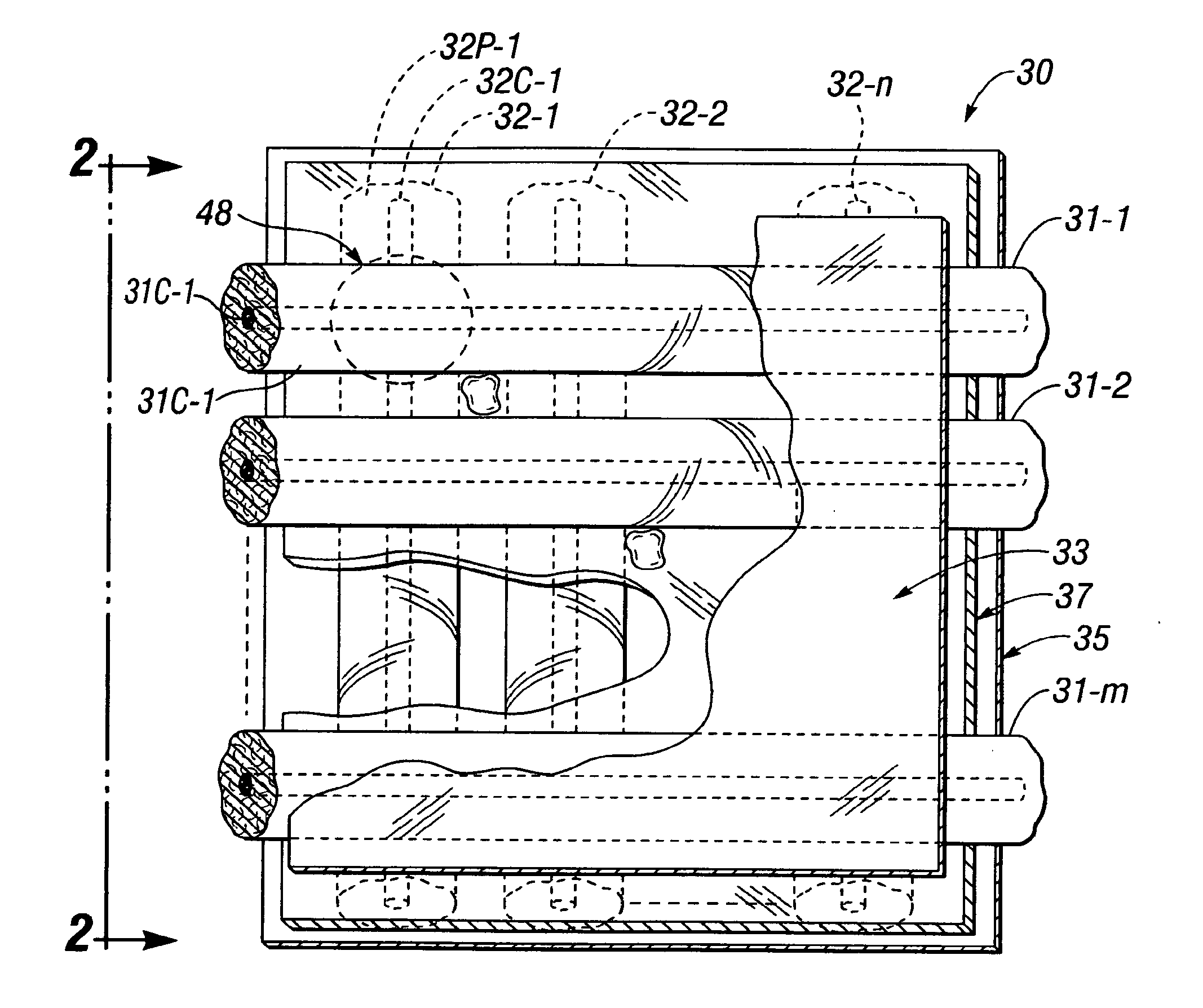
  • Elastically stretchable fabric force sensor arrays and methods of making
  • Elastically stretchable fabric force sensor arrays and methods of making
  • Elastically stretchable fabric force sensor arrays and methods of making

Examples


example i

[0135 for forces in the range of 0 to 30 psi:[0136]−200 ml of acrylic binder[0137]−10 ml of nickel flake powder[0138]−10 ml of graphite powder[0139]−20 ml of carbon black

example ii

[0140 for forces in the range of 0-100 psi[0141]−200 ml of acrylic binder[0142]−5 ml of nickel flake powder[0143]−5 ml of graphite powder[0144]−30 ml of carbon black

[0145]Example III for forces in the range of 0-1000 psi[0146]−200 ml of acrylic binder[0147]−1 ml of nickel flake powder[0148]−1 ml of graphite powder[0149]−40 ml of carbon black

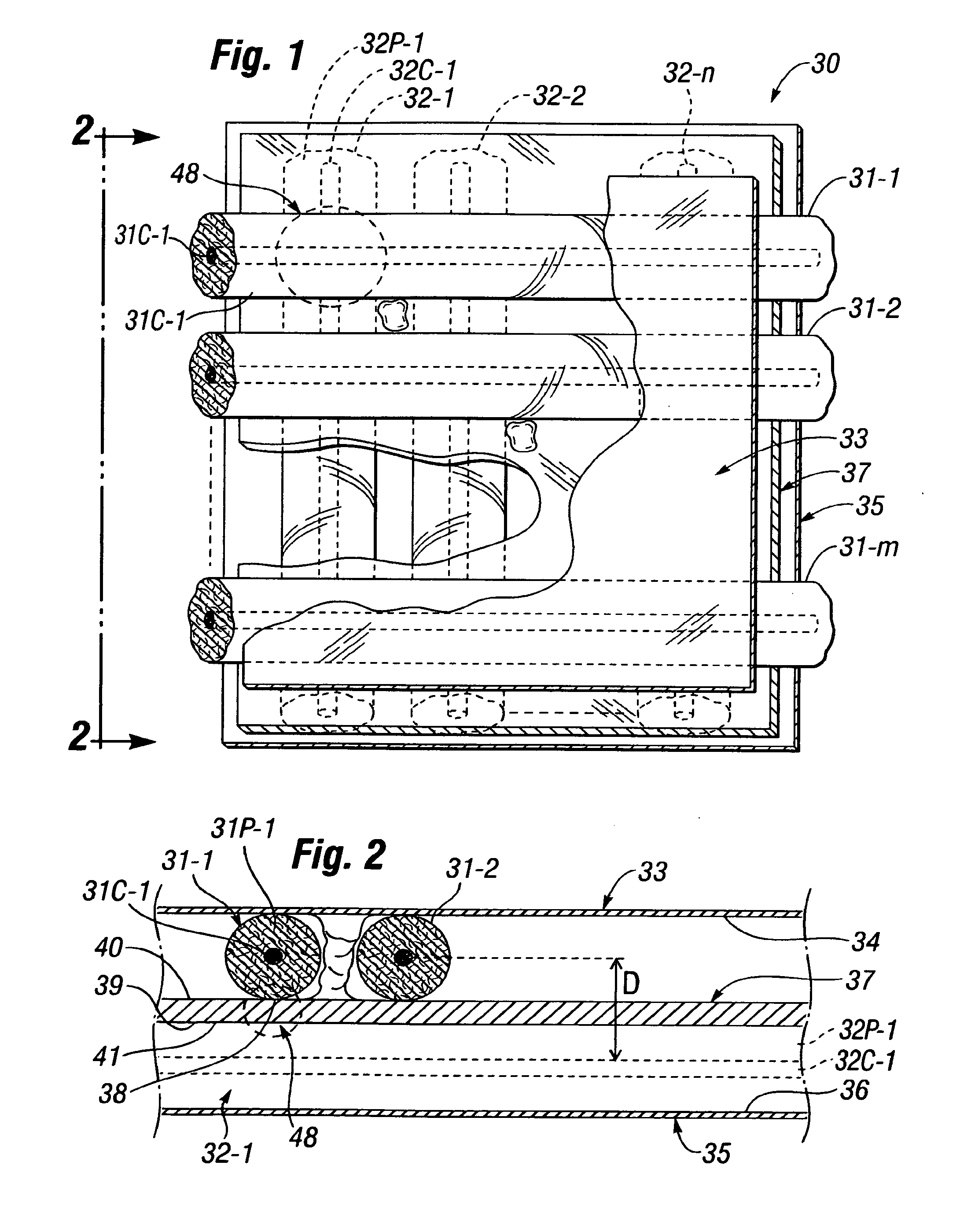
[0150]The fabric matrix for piezoresistive sheet 37 is submerged in the piezoresistive coating mixture. Excess material is rolled off and the sheet is hung and allowed to air dry.

[0151]According to the invention, upper and lower substrate sheets 33, 34 are made of a thin, flexible insulating material, such as 0.002 inch thick polyurethane or polyvinyl chloride (PVC). Preferably, the substrate sheets 33, 34 are made of an elastomeric material which has a relatively high degree of elastic stretchability, so that sensor array 30 is readily stretchable and conformable to the surface of an irregularly-shaped object. It can be appreciated, however, tha...

embodiment 50

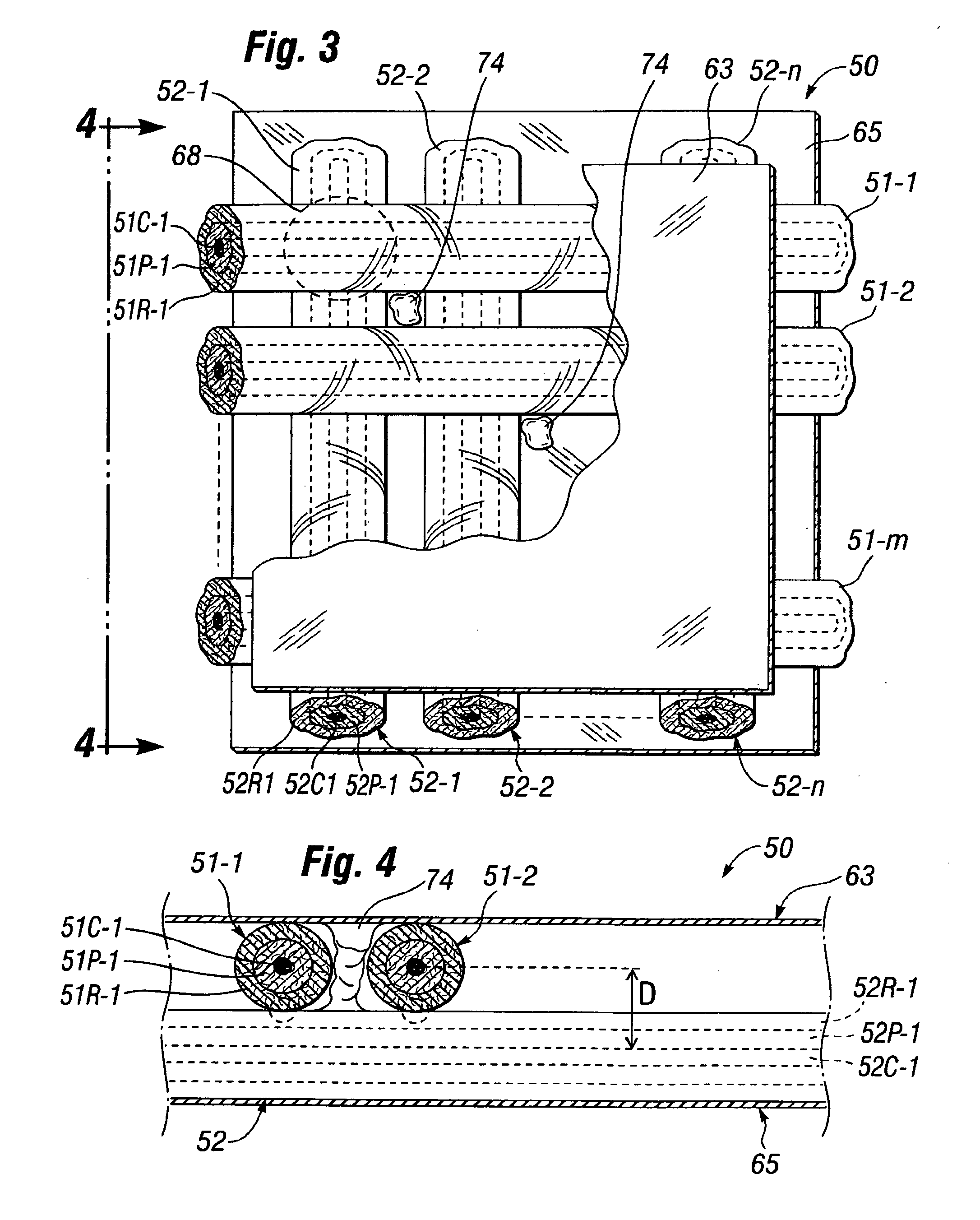
[0158]FIGS. 3 and 4 illustrate another embodiment 50 of a piezoresistive thread pressure sensor array according to the present invention, in which the central piezoresistive layer shown in FIGS. 1 and 2 and described above is replaced by a piezoresistive coating on either, or preferably both, row conductive threads 51 and column conductive threads 52.

[0159]Sensor array 50 is facially similar to sensor array 20 disclosed and shown in FIGS. 1 and 2 of U.S. Pat. No. 6,543,299, but differs from that sensor array in important ways. Thus, row and column piezoresistive threads 51, 52 of sensor array 50 are made of elastically stretchable polymer cores 51C, 52C which have been treated by silver plating the cores to form on the threads electrically conductive coatings 51P, 52P, respectively. The coatings on either or both cores 51C, 52C are clad with a layer 51R, 52R, respectively, of a material which has a piezoresistive characteristic. According to the invention, the piezoresistive materia...


PUM

PropertyMeasurementUnit
diameteraaaaaaaaaa
thicknessaaaaaaaaaa
diameteraaaaaaaaaa

Abstract

Force or pressure transducer arrays have elastically stretchable electrically conductive polymer threads disposed in parallel rows and columns that contact at intersections thereof a piezoresistive material which has an electrical resistivity which varies inversely with pressure or force exerted thereon to form a matrix array of force or pressure sensor elements. The threads are fixed to a single one or pair of flexible elastically stretchable substrate sheets made of thin sheets of an insulating polymer such as PVC, or for greater elasticity and conformability to irregularly-shaped objects such as human body parts, an elastically stretchable fabric such as LYCRA or SPANDEX. Elastic stretchability of the sensor arrays is optionally enhanced by disposing either or both row and column conductive threads in sinuously curved, serpentine paths rather than straight lines.

Description

CROSS-REFERENCE TO RELATED APPLICATIONS[0001]This application is a continuation of, and claims priority to, U.S. patent application Ser. No. 12 / 380,845 filed Mar. 5, 2009, and entitled ELASTICALLY STRETCHABLE FABRIC FORCE SENSOR ARRAYS AND METHOD OF MAKING, by applicant Geoffrey Taylor, which is incorporated by reference herein in its entirety.BACKGROUND OF THE INVENTION[0002]A. Field of the Invention[0003]The present invention relates to transducers or sensors used to measure forces or pressures exerted on a surface. More particularly, the invention relates to fabric force sensor arrays which use elastically stretchable piezoresistive thread sensor elements and are sufficiently conformable to irregularly-shaped objects to be incorporated into clothing wearable by people, and methods of making such arrays.[0004]B. Description of Background Art[0005]Whenever a human body is supported by an object such as a chair or bed, normal and shear forces produced in reaction to the weight of th...

Claims


Application Information

Patent Timeline
Patent Type & Authority Applications(United States)
IPC IPC(8): G01L1/18
CPCG01L1/18G01L1/205A47C27/082G01N2203/0623H01L29/84G01N3/08G01L1/20G01L5/228A61B5/1036A61B5/6892A61B2562/046G01L1/16A61B2562/0247
Inventor TAYLOR, GEOFFREY L.
Owner PATIENTECH LLC
Learn More