Method of determining an amount of impurities that a contaminating material contributes to high purity silicon and furnace for treating high purity silicon

a technology of impurities and contaminating materials, which is applied in the field of determining the amount of impurities that a contaminating material contributes to high purity silicon and the treatment of high purity silicon furnace, can solve the problems of environmental impurities, brittle polycrystalline silicon logs, and brittle polycrystalline silicon logs, and achieves the effect of reducing the amount of impurities present, high purity composition, and high purity composition

Inactive Publication Date: 2012-09-13
HEMLOCK SEMICONDUCTOR CORPORATION
View PDF7 Cites 3 Cited by
  • Summary
  • Abstract
  • Description
  • Claims
  • Application Information

AI Technical Summary

Benefits of technology

[0011]A furnace assembly of the present invention for heat treating a high purity composition comprises a base presenting a hearth for receiving the high purity composition. The base has a periphery. The base also has a seating surface that is defined adjacent to the periphery. A furnace cover that is separate from the base defines a cavity. The furnace cover further defines an opening to the cavity. The base abuts the furnace cover at the seating surface when the furnace cover is disposed on said base, thereby sealing the cavity and forming a heating chamber. The base and the furnace cover are separable for enabling the furnace cover to be removed from the base during insertion and removal of the high purity composition from the heating chamber.
[0012]The method of determining the amount of impurities that a contaminating material including the impurities contributes to high purity silicon, as well as the furnace and the furnace assembly of the instant invention, each provide advantages in that each plays a role to reduce the amount of impurities present in high purity compositions, such as high purity crystalline silicon compositions, by focusing on aspects of the step of annealing. For example, the method may be used to determine optimum materials for various components of furnaces and furnace assemblies based on the amount of impurities that tested materials contribute to high purity silicon, thereby minimizing contribution of impurities from the materials of the furnace itself. As such, determinations made from the method may be used to design furnaces and furnace assemblies having the housing that is at least partially formed from low contaminant material, i.e., determinations made from the method may be used to identify the low contaminant material. Finally, the furnace assemblies in accordance with the instant invention minimize dust generation due to movement of various components of the furnace assemblies or due to movement necessary to introduce the high purity compositions into the furnace. By providing the furnace cover separate from the base, the furnace cover can be vertically lifted and lowered onto the base, thereby eliminating lateral movement that is more likely to disturb dust and other debris that could be disposed on the furnace cover. The combined effect of the method, the furnace, and the furnace assembly of the instant invention is to minimize the amount of impurities that are contributed to high purity compositions, especially high purity crystalline silicon, when the high purity compositions are heated in the furnace.

Problems solved by technology

However, the polycrystalline silicon logs are brittle and must be annealed to reduce internal stresses, which enables the polycrystalline silicon logs to be effectively cut into silicon slim rods without breaking.
However, annealing contributes impurities to the polycrystalline silicon logs, which is undesirable.
More specifically, environmental impurities, such as dust or other molecules present in the ambient atmosphere, may contaminate the polycrystalline silicon logs during annealing.
Furthermore, materials that are actually used to form the furnace and that are heated during annealing release impurities contained therein.

Method used


Image

  • Method of determining an amount of impurities that a contaminating material contributes to high purity silicon and furnace for treating high purity silicon
  • Method of determining an amount of impurities that a contaminating material contributes to high purity silicon and furnace for treating high purity silicon
  • Method of determining an amount of impurities that a contaminating material contributes to high purity silicon and furnace for treating high purity silicon

Examples


examples

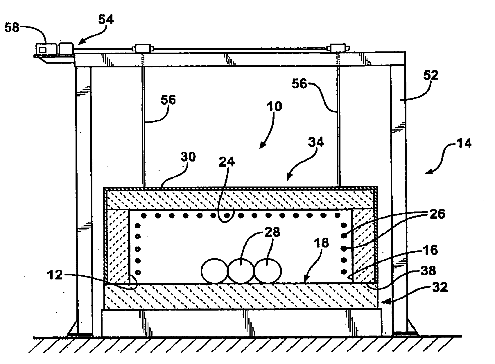
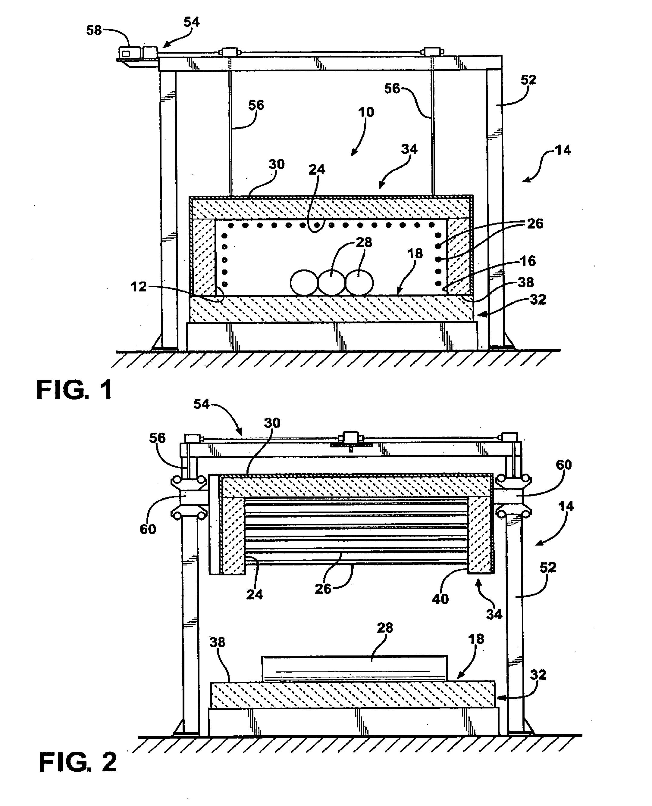
[0047]Various contaminating materials including impurities are tested in accordance with the method of the instant invention to determine an amount of impurities that the contaminating materials contribute to high purity silicon. More specifically, high purity silicon having an impurity content of less than or equal to 500 ppta is encased in various materials to determine the amount of impurities that the contaminating materials contribute to the high purity silicon. The samples encased in the contaminating material are heated at an annealing temperature for a sufficient period of time to anneal the high purity silicon.

[0048]Based on the determinations made relative to the amount of impurities that the contaminating materials contributes to high purity silicon, low contaminating materials are identified and used to form various components of a housing of a furnace. In particular, the housing is formed from the following components and materials:

ComponentMaterialHot FacePyroblock ® M...


PUM

PropertyMeasurementUnit
temperatureaaaaaaaaaa
temperaturesaaaaaaaaaa

Abstract

A method of determining an amount of impurities that a contaminating material contributes to high purity silicon comprises the step of partially encasing a sample of high purity silicon in the contaminating material. The sample encased in the contaminating material is heated within a furnace. A change in impurity content of the high purity silicon is determined after the step of heating, compared to an impurity content of the high purity silicon prior to the step of heating.

Description

BACKGROUND OF THE INVENTION[0001]1. Field of the Invention[0002]The subject application generally relates to a method of determining an amount of impurities that a contaminating material contributes to a high purity silicon that is heated in the presence of the material, and is further directed to furnace that minimizes the amount of impurities that are contributed from the furnace to the high purity silicon.[0003]2. Description of the Related Art[0004]Methods of processing high purity compositions are known in the art, especially in the semiconductor industry where it is desirable to manufacture high purity crystalline silicons. The amount of impurities in the high purity crystalline silicons directly correlates to performance of the high purity crystalline silicons in semiconductors. Therefore, there is a constant desire to minimize impurity content of the high purity crystalline silicons, as well as a general desire to minimize impurity content in any high purity composition.[000...

Claims


Application Information

Patent Timeline
Patent Type & Authority Applications(United States)
IPC IPC(8): G01N1/44
CPCC01B33/021C01B33/037C30B29/06F27D2019/0006C30B35/00F27B17/0033F27D19/00C30B33/02
Inventor DEPASA, DENNISHOST, JONHOUTHOOFD, TROYRYTLEWSKI, ALAN
Owner HEMLOCK SEMICONDUCTOR CORPORATION
Why Eureka
Try Eureka