
Wavelength converting member and light source device

a technology of light source and converting member, which is applied in semiconductor lasers, lighting and heating apparatuses, instruments, etc., can solve the problems of laser light damage to human eyes, risk of causing a biochemical reaction with eyes or retinas, burnt residue of resin binder, etc., to improve the color mixing ability of emitted colors and ensure the safety of human eyes

Inactive Publication Date: 2012-09-06
STANLEY ELECTRIC CO LTD
View PDF16 Cites 57 Cited by
  • Summary
  • Abstract
  • Description
  • Claims
  • Application Information

AI Technical Summary

Benefits of technology

[0010]It is an object of the present invention to provide a wavelength converting member that can ensure safety to human eyes and improve color mixing ability of emitted colors.
[0014]With the wavelength converting member and light source device in accordance with the present invention, it is possible to ensure safety to human eyes and improve color mixing ability of emitted colors.

Problems solved by technology

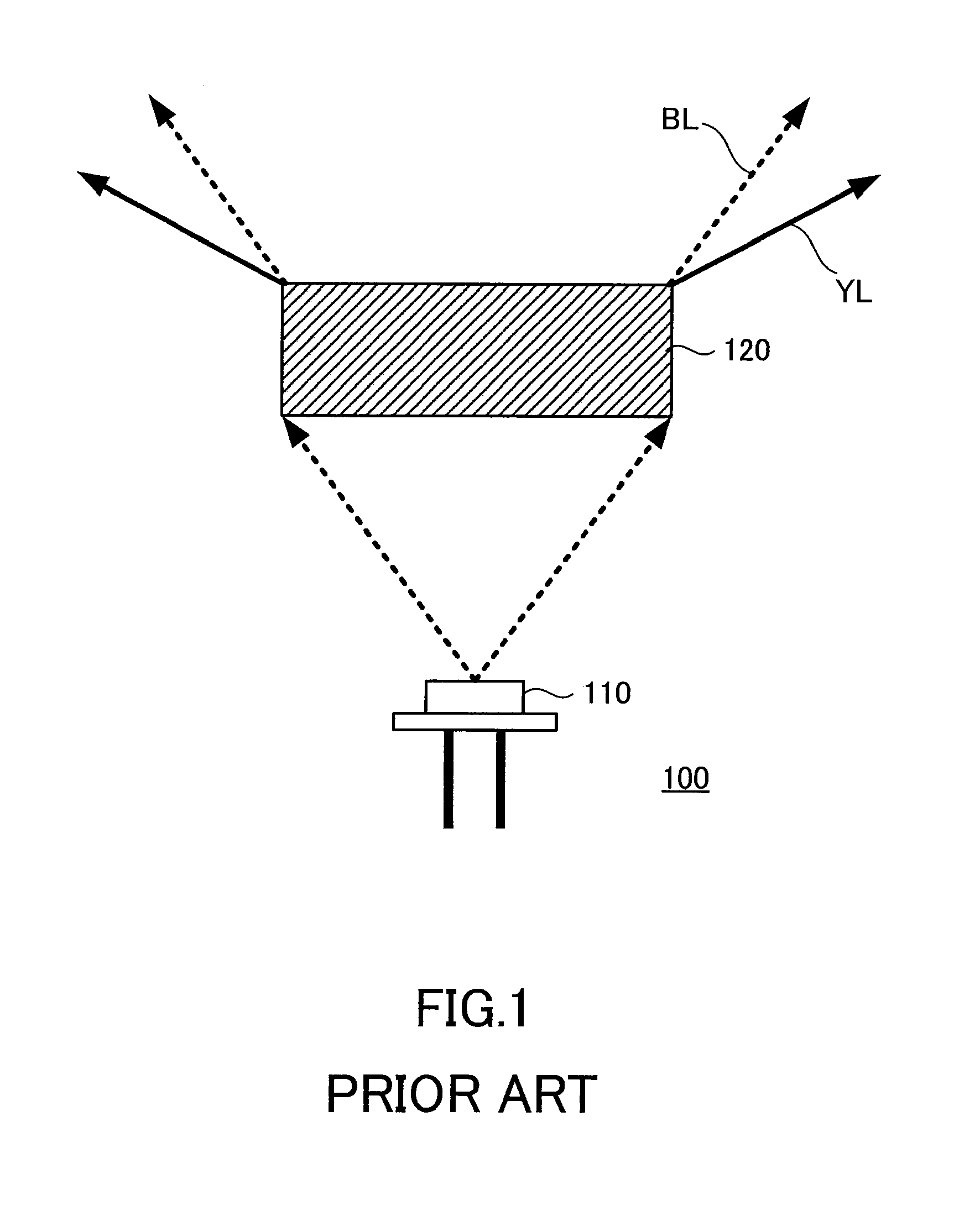
However, the resin binder is burned out when a phosphor layer using a resin binder is irradiated with a high-output laser light.
Therefore, the laser light can damage human eyes.
In the case of a visible light laser, there is also a risk of causing a biochemical reaction with the eye or retina.
As such, the retina can be damaged even when the total light power is small.
When such light is focused by an optical system, the focused light can produce a spot size at the laser emission aperture which can be dangerous for human eyes.

Method used


Image

  • Wavelength converting member and light source device
  • Wavelength converting member and light source device
  • Wavelength converting member and light source device

Examples


embodiment 1

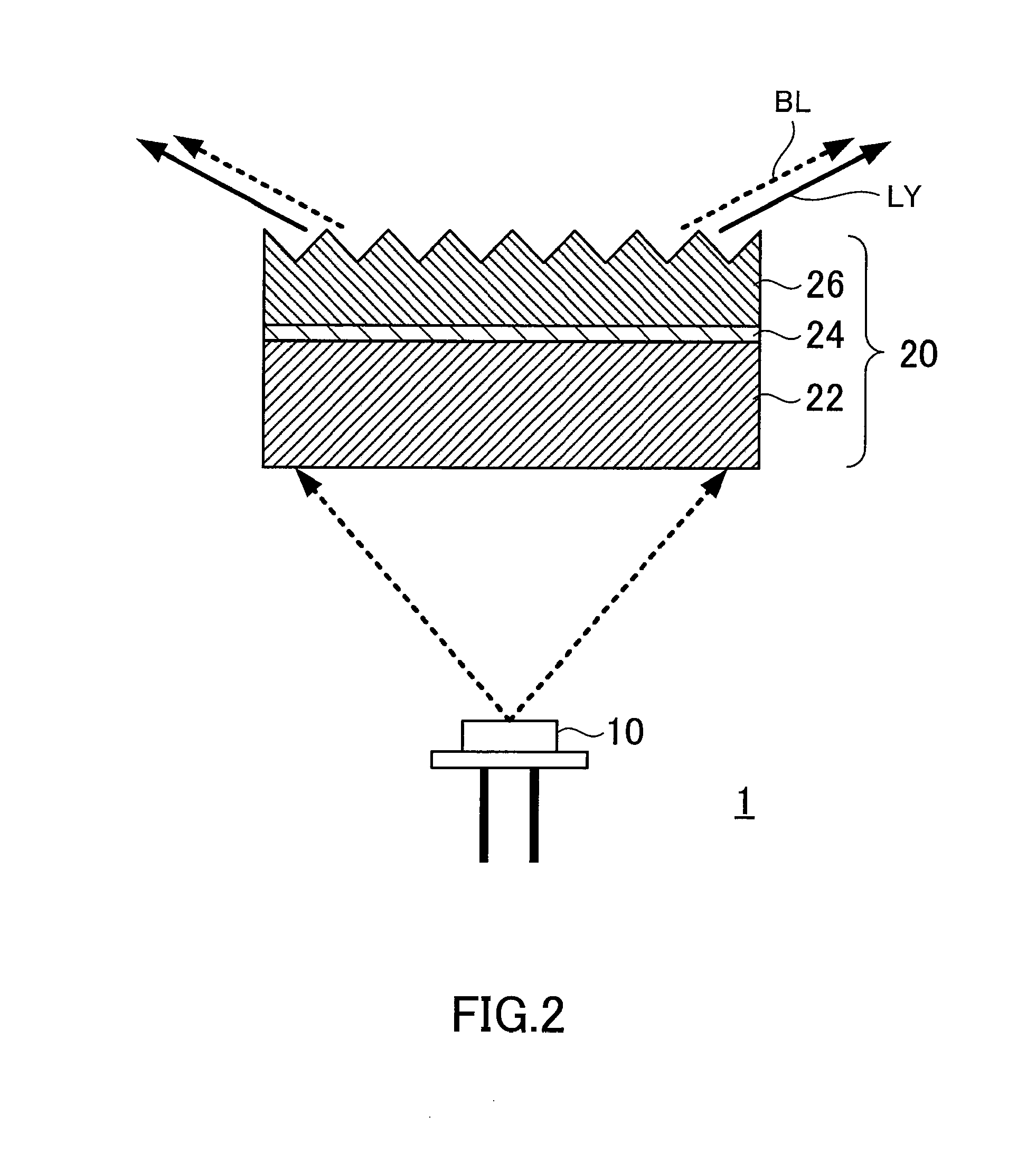
[0025]Referring to FIG. 2, the configuration of a light source device 1 according to a first embodiment of the present invention will be described. The light source device 1 includes a semiconductor laser 10 that is adapted to emit a laser light and a wavelength converting member 20 that receives the laser light and radiates light with a wavelength longer than that of the laser light.

[0026]The semiconductor laser 10 is a light-emitting element including, for example, a GaN-based nitride semiconductor layer. This semiconductor layer possesses a multiple quantum well structure and radiates blue light with a wavelength of about 450 nm. It should be noted that the light emission wavelength, material, and layer structure of the semiconductor laser 10 are not limited to those mentioned above and may be suitably selected depending on its application and / or given conditions.

[0027]The wavelength converting member 20 receives the laser light emitted from the semiconductor laser 10. The wavele...

embodiment 2

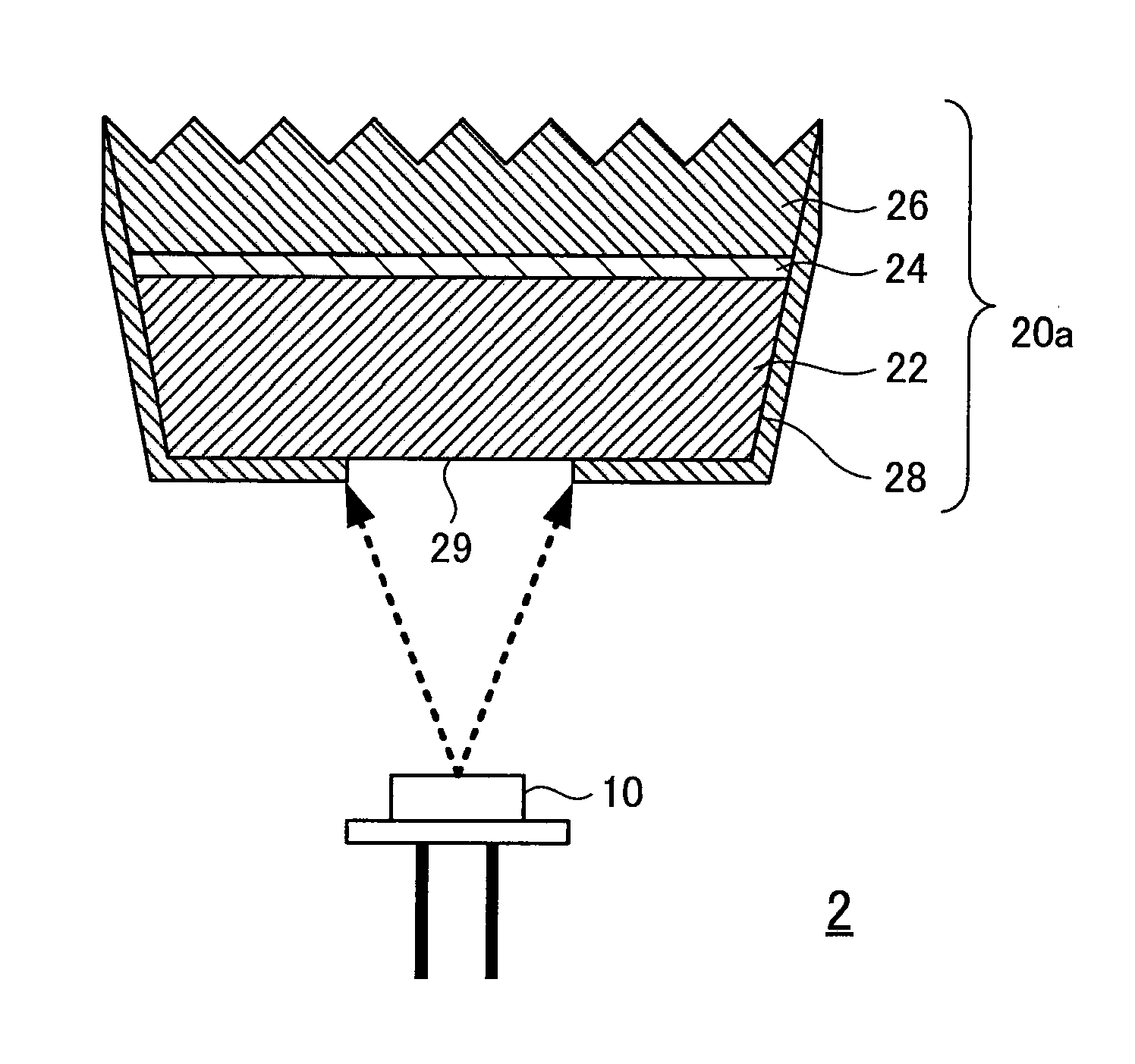
[0043]FIG. 5 shows the configuration of a light source device 2 according to Embodiment 2 of the present invention. The configuration of the wavelength converting member 20a of the light source device 2 is different from that of Embodiment 1. A wavelength converting member 20a has a light reflecting film 28 on part of the laser light incidence surface and the surface excluding the entire light extraction surface. Thus, the light reflecting film 28 covers the side surface of the wavelength converting member 20a and part of the bottom surface of the phosphor layer 22, which is the laser light incidence surface. The portion of the laser light incidence surface where the light reflecting film 28 has not been formed is a laser light incidence port or opening 29 for introducing (or receiving) the laser light into the wavelength converting member 20a. The light reflecting film 28 is made from a metal having light reflecting ability, for example, from a multilayer film obtained by successiv...


PUM

PropertyMeasurementUnit
Poweraaaaaaaaaa
Diameteraaaaaaaaaa
Heightaaaaaaaaaa

Abstract

A wavelength converting member radiates light having a wavelength different from that of laser light introduced into the wavelength converting member. The wavelength converting member has a phosphor layer that contains a phosphor therein. The phosphor layer has a laser light incidence surface capable of receiving the laser light. The wavelength converting member also has a high-refractive layer that is bonded to an opposite surface of the phosphor layer to the laser light incidence surface thereof. A refractive index of the high-refractive layer is higher than a refractive index of the phosphor layer. The high-refractive layer has concaves on at least either the bonding surface where the high-refractive layer is bonded to the phosphor layer or a light extraction surface that is opposite the bonding surface.

Description

BACKGROUND OF THE INVENTION[0001]The present invention relates to a light source device using a semiconductor laser.[0002]Semiconductor lasers have an electricity-light conversion efficiency higher than that of light-emitting diodes and can ensure a high output. Accordingly, they are expected to find use as light sources for projectors or high-luminance white light sources such as automobile headlights. When a semiconductor laser is used to obtain white light, a blue semiconductor laser is combined with a wavelength converting member including a phosphor. A phosphor layer is irradiated with a blue laser light, wavelength conversion is performed by the phosphor to a longer wavelength range, and the resulting wavelength-converted light is mixed with light that has been transmitted, without wavelength conversion, through the phosphor layer, thereby producing white light.[0003]Japanese Patent No. 4,054,594 or Japanese Patent Application Publication (Kokai) No. 2003-295319 discloses a li...

Claims


Application Information

Patent Timeline
IPC IPC(8): F21V13/14F21V13/02C09K11/00G02B1/11G02B1/115H01S5/50
CPCC09K11/7774H01S5/32341H01S5/005H01S5/0087
Inventor KOIKE, TERUOLIANG, JI-HAO
Owner STANLEY ELECTRIC CO LTD
Learn More