Eureka AIR delivers breakthrough ideas for toughest innovation challenges, trusted by R&D personnel around the world.

Thermal processing apparatus and method of controlling the same

a technology of processing apparatus and temperature, which is applied in the direction of lighting and heating apparatus, muffle furnaces, furnaces, etc., can solve the problems of difficult control of temperature and time-consuming tuning, and achieve the effect of improving temperature uniformity and facilitating control of temperature in the furnace body

Active Publication Date: 2012-09-06
TOKYO ELECTRON LTD
View PDF2 Cites 10 Cited by
  • Summary
  • Abstract
  • Description
  • Claims
  • Application Information

AI Technical Summary

Benefits of technology

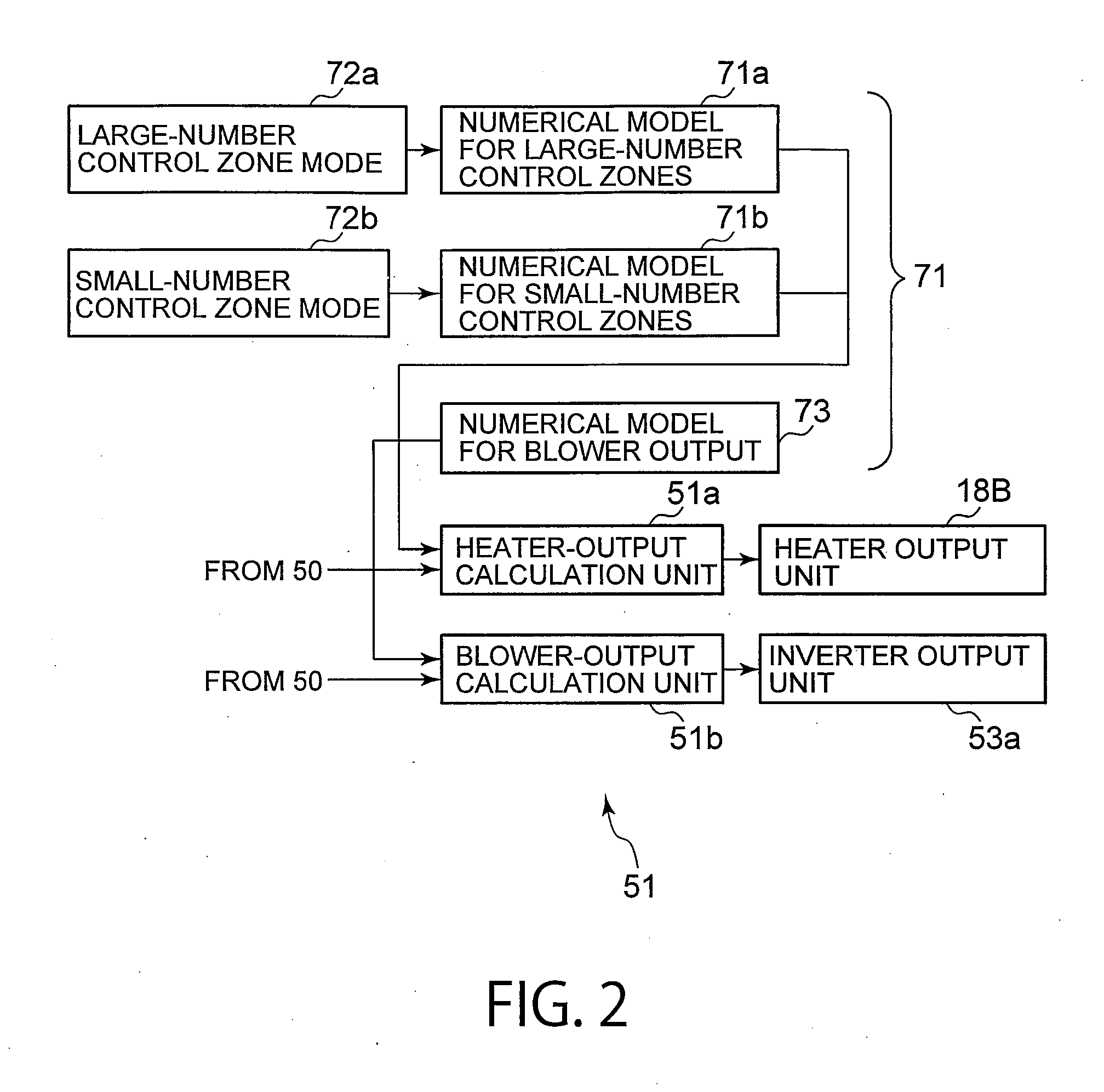
The patent describes a thermal processing apparatus with a furnace body and a processing vessel. The apparatus has a control unit that can control the heating units of the processing vessel based on signals from temperature sensors in the processing vessel. The control unit can select between a large-number control zone mode and a small-number control zone mode. In the large-number mode, there are many control zones, and in the small-number mode, there are fewer control zones. The control unit can also control the blower to supply cooling medium to the space between the furnace body and the processing vessel. The technical effect of this patent is to provide a thermal processing apparatus with improved control over the heating units and the blower, allowing for better temperature control and more efficient processing.

Problems solved by technology

However, when the inside space of the furnace body is divided into the plurality of control zones, and the respective control zones are finely controlled, a problem occurs in that it is difficult to control a temperature when it is increased or decreased so that it takes a lot of time to tune control parameters, although a temperature uniformity can be improved when the temperature is stabilized.Patent Document 1: JP2002-305189APatent Document 2: JP2005-188869A

Method used


Image

  • Thermal processing apparatus and method of controlling the same
  • Thermal processing apparatus and method of controlling the same
  • Thermal processing apparatus and method of controlling the same

Examples


Embodiment Construction

Embodiment of the Invention

[0036]An embodiment of the present invention will be described herebelow with reference to the drawings.

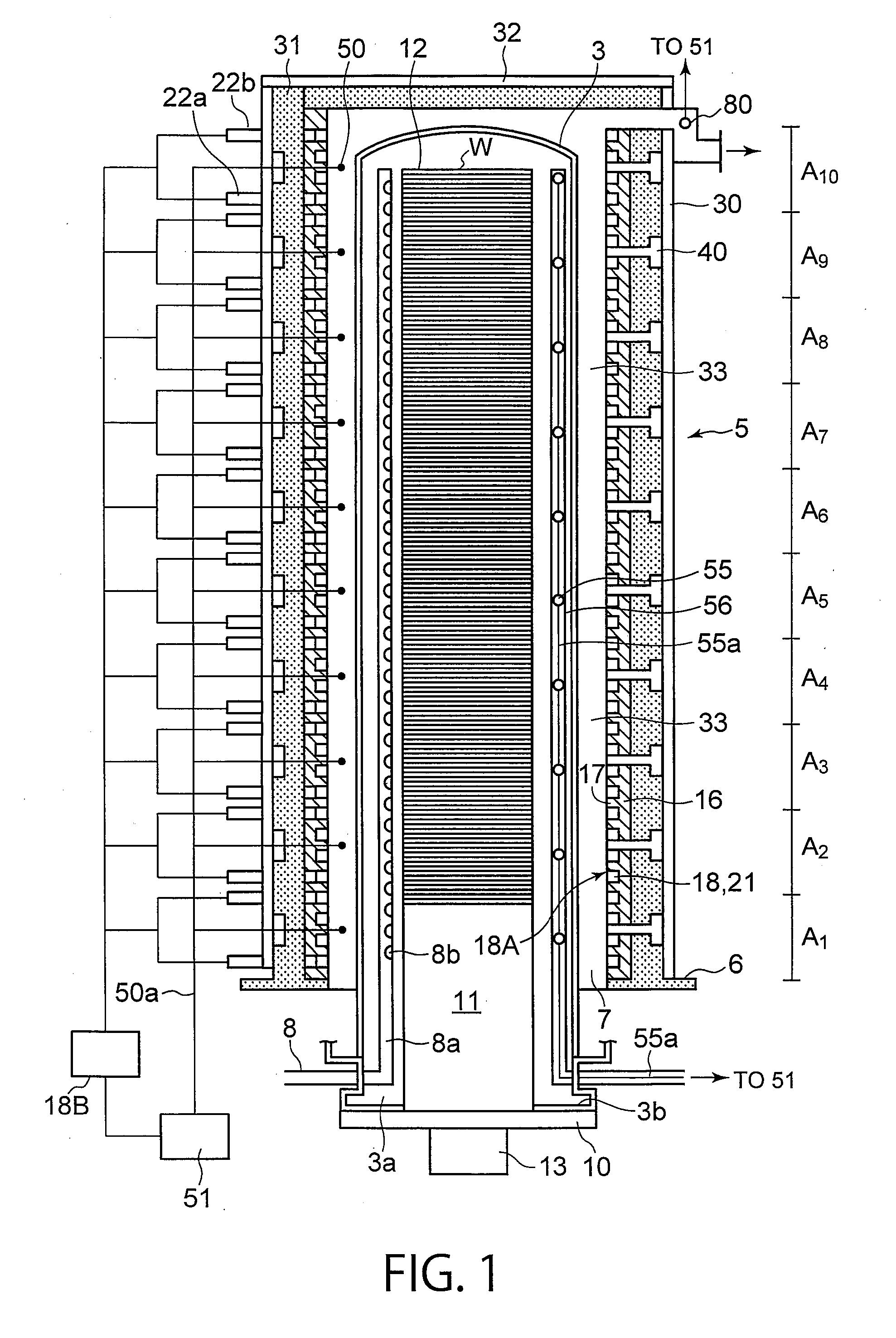
[0037]In FIG. 1, a vertical-type thermal processing apparatus 1 includes a vertical-type thermal processing furnace 2 capable of simultaneously accommodating a number of objects to be processed, e.g., semiconductor wafers w, and of subjecting the semiconductor wafers w to various thermal processes such as an oxidation process, a diffusion process, a low-pressure CVD process and so on. The thermal processing furnace 2 includes a furnace body 5 and a processing vessel 3 disposed in the furnace body 5 so as to define a space 33 between the processing vessel 3 and the furnace body 5. A plurality of heating resistors (heaters) 18A serving as a heating unit are disposed on an inner circumferential surface of the thermal processing furnace 2. The processing vessel 3 is configured to accommodate and thermally process wafers w.

[0038]The space 33 between the furna...


PUM


Abstract

A control unit can select a large-number control zone model in which the number of control zones, which are independently controlled, is large, and a small-number control zone model in which the number of control zones, which are independently controlled, is small. When a temperature is increased or decreased, the control unit can select the small-number control zone model so as to control, based on signals from temperature sensors of the respective control zones C1 . . . C5 whose number is small, heaters located on the respective control zones C1 . . . C5. When a temperature is stabilized, the control unit can select the large-number control zone model so as to control, based on signals from the temperature sensors of the respective control zones C1 . . . C10 whose number is large, the heaters located on the respective control zones C1 . . . C10.

Description

CROSS REFERENCE TO RELATED APPLICATIONS[0001]This application is based upon and claims the benefit of priority from the prior Japanese Patent Application No. 2011-044197 filed on Mar. 1, 2011, the entire contents of which are incorporated herein by reference.FIELD OF THE INVENTION[0002]The present invention relates to a thermal processing apparatus and a method of controlling the same.BACKGROUND OF THE INVENTION[0003]In the manufacture of semiconductor devices, various thermal processing apparatuses are used for subjecting objects to be processed, such as semiconductor wafers, to thermal processes such as an oxidation process, a diffusion process, a CVD process and an annealing process. As one of such processing apparatuses, there is known a vertical-type thermal processing apparatus capable of thermally processing a number of objects to be processed at once. The vertical-type thermal processing apparatus includes: a quartz processing vessel having a lower opening; a lid member conf...

Claims


Application Information

Patent Timeline
Patent Type & Authority Applications(United States)
IPC IPC(8): F27B5/18F27D21/00F27B5/14F27D11/02
CPCF27B17/0025F27D19/00H01L21/67115H01L21/67109H01L21/67248F27D21/0014
Inventor YOSHII, KOJIYAMAGUCHI, TATSUYAWANG, WENLINGSAITO, TAKANORI
Owner TOKYO ELECTRON LTD
Why Eureka
Eureka Blog
Learn More