
Hydraulic Control Device for Hybrid Transmission

a technology of hydraulic control device and hybrid transmission, which is applied in the direction of gearing control, clutch, gearing element, etc., can solve the problems of not being suitable for hydraulic control device used with hybrid transmission, such as the inability to comprehensively popularize such vehicles in a short time, and the inability to integrate hydraulic control device for hybrid transmission, etc., to achieve the effect of improving the braking performan

Active Publication Date: 2012-08-23
CORUN CHS TECH CO LTD
View PDF0 Cites 8 Cited by
  • Summary
  • Abstract
  • Description
  • Claims
  • Application Information

AI Technical Summary

Benefits of technology

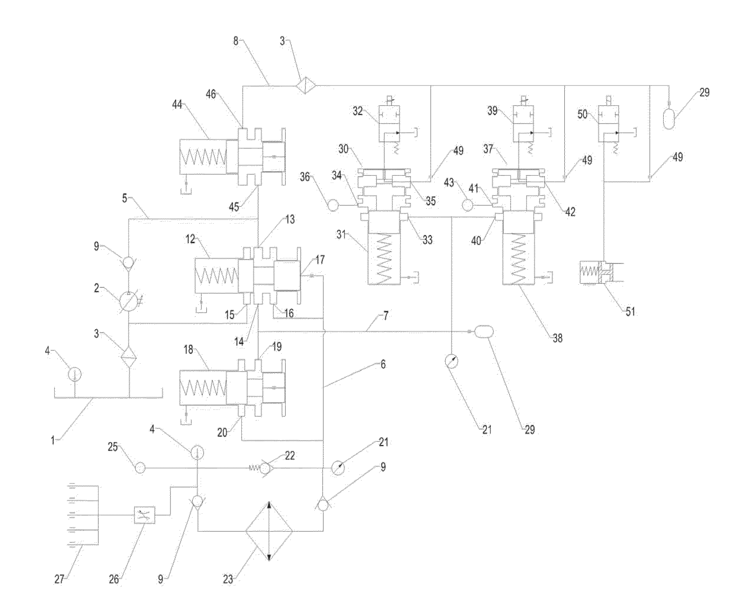
[0008]The hydraulic control device for a hybrid transmission according to the invention divides the main oil line into the cooling and lubrication oil line, the clutch control oil line and the solenoid control oil line, thereby can meet the needs of the hybrid transmission for hydraulic control. The first and second lock-up clutches used for locking the engine or motor of the hybrid transmission can be controlled through the clutch control oil line, thereby achieving a better control of the transmission operation condition, and increasing its transmission efficiency. A pressure release valve and an overflow valve can be used to define the pressure in the main oil line, ensuring the normal operation of the hydraulic control device. As the oil orifice on the pressure release valve is directly connected to the cooling and lubrication oil line, the cooling and lubrication oil line would have been in oil communication even when the main oil line pressure of the hydraulic control device does not reach the set pressure of the overflow valve, so that the transmission can be lubricated quickly. The cooler provided on the cooling and lubrication oil line can cool the oil temperature of the oil line, thereby increasing the cooling effect on the motor. The oil orifice has a damping depressurization effect when hydraulic oil passes, the outlet pressure of the solenoid control oil line after the oil orifice is thus greatly reduced. The oil return to the oil tank after passing a pilot valve of the proportional pressure reducing valve connected therewith, when the pilot valve of the proportional pressure reducing valve is powered on, the oil line thereof is totally sealed, the outlet pressure of the oil orifice is thus increased, and the valve spool of the main valve of the proportional pressure reducing valve is forced to act, causing the proportional pressure reducing valve to open and achieving the function of locking the engine or motor. Due to the hysteresis effect of the proportional pressure reducing valve, the transient braking of the lock-up clutch is avoided. Moreover, the solenoid control oil line connects to the switch solenoid and the parking lock hydraulic oil cylinder through the oil orifice respectively, so the hydraulic oil passing the oil orifice directly returns to the oil tank through the switch solenoid before the switch solenoid is powered on. After the switch solenoid is powered on, its valve spool moves to totally seal the oil line, then the outlet pressure of the oil orifice rises, in turn forces the parking lock hydraulic oil cylinder to act, achieving the parking lock function.
[0010]As a preference, an accumulation shock absorber is provided on the clutch control oil line and the solenoid control oil line respectively, thereby reducing the pressure fluctuation.
[0014]To sum up, the invention has the following beneficial effects: (1) the cooling and lubrication oil line of the system being in an oil communication even before the main oil line pressure reaches the set pressure of the overflow valve, so as to lubricate the transmission as soon as possible; (2) providing an overpressure protection for the cooler; (3) using a proportional pressure reducing valve to control the lock-up clutch, thus making for the improvement of its braking performance.

Problems solved by technology

However, due to various constraints on the technology, vehicles of such types are difficult to be comprehensively popularized in a short time.
But so far an integrated hydraulic control device for a hybrid transmission has not been appeared.
CN1862062A, these are not suitable for hydraulic control device used with hybrid transmissions.

Method used


Image

  • Hydraulic Control Device for Hybrid Transmission
  • Hydraulic Control Device for Hybrid Transmission

Examples


Embodiment Construction

[0016]The following detailed description is merely exemplary in nature and not intended to limit the application or use. Moreover, the invention is not intended to be constrained by any theories stated or suggested in previous Technical Field, Background, and Summary of the invention or the following descriptions.

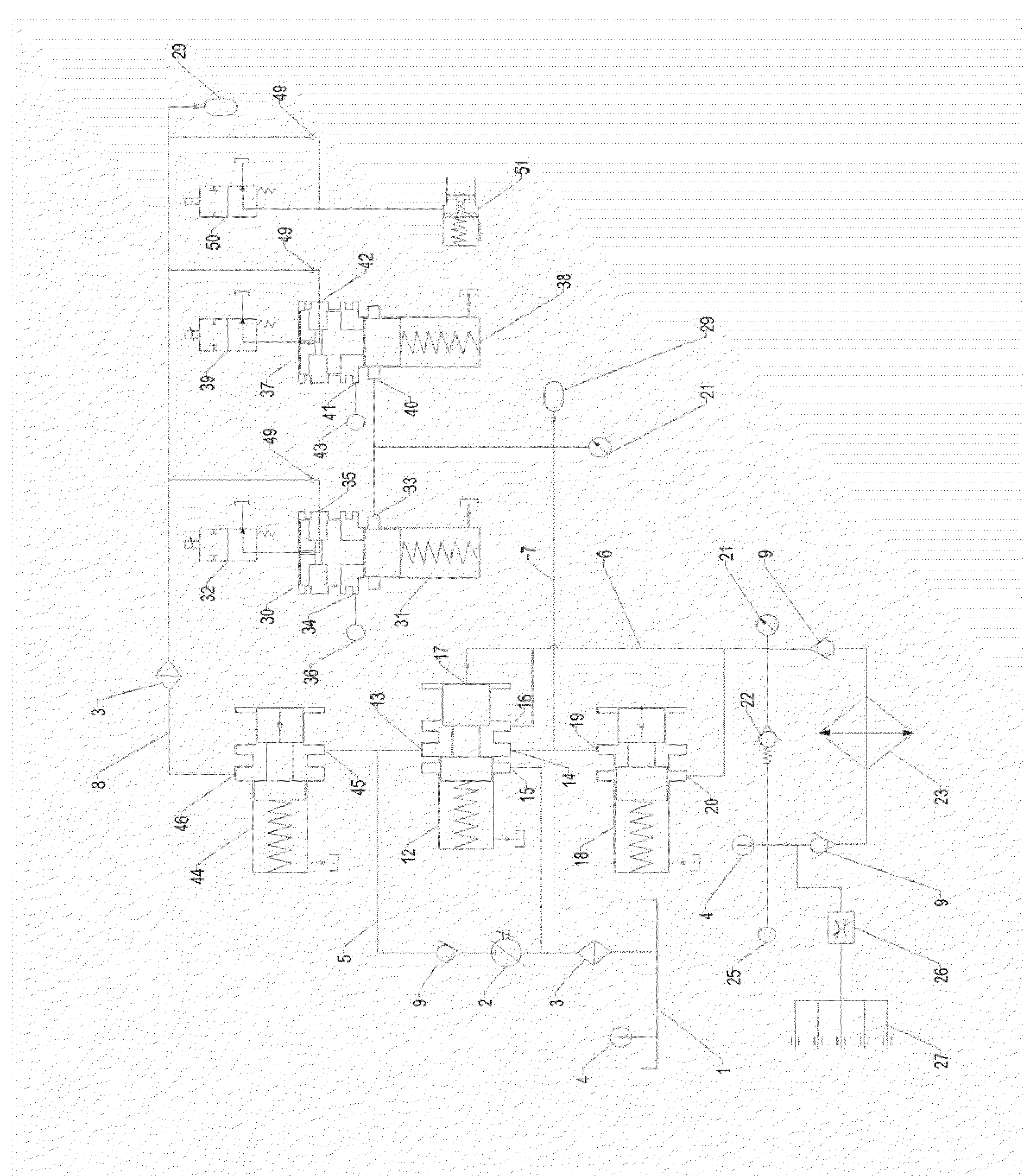
[0017]In the embodiment shown in FIG. 1, the hydraulic control device for a hybrid transmission according to the invention comprises an oil tank 1 and a corresponding oil pump 2. A filter 3 is provided in front of the oil pump 2, a temperature sensor 4 is provided within the oil tank 1 to facilitate the temperature control.

[0018]A check valve 9 is provided on the main oil line 5 on the outlet end of the oil pump 2, to prevent the fuel from returning. The main oil line 5 connects to the oil inlet 13 of an unloading valve 12 and an oil inlet 45 of a pressure reducing valve 44 respectively. The oil outlet 14 of the unloading valve connects to the oil inlet 19 of an overflow va...


PUM


Abstract

A hydraulic control device for a hybrid transmission is designed such that the cooling and lubrication oil line of the system are in oil communication even before the main oil line pressure reaches the set pressure of the overflow valve, so as to lubricate the transmission as soon as possible. The hybrid transmission design further provides an overpressure protection for the cooler. The hybrid transmission further uses a proportional pressure reducing valve to control the lock-up clutch, thus making for the improvement of its braking performance.

Description

TECHNICAL FIELD[0001]The invention relates to a hydraulic control device for a vehicle, in particular, to a hydraulic control device used with a hybrid transmission of a hybrid electrical vehicle.BACKGROUND[0002]Due to short of energy, enhancement of the public environmental awareness, and increasingly strict regulations of the government, environment friendly electrical vehicle and fuel cell vehicle emerge. However, due to various constraints on the technology, vehicles of such types are difficult to be comprehensively popularized in a short time. Therefore, a hybrid electrical vehicle which has been relatively mature in technology is a comparatively desired choice at present.[0003]As transmissions of a hybrid electrical vehicle mostly employ a planet gear transmission mechanism, such as the hybrid transmission of the Toyota hybrid electrical vehicle Prius, to realize a continuously variable speed change, typically in this type of transmission a hydraulic control device such as pro...

Claims


Application Information

Patent Timeline
IPC IPC(8): B60W10/196B60W10/10
CPCF16H61/0206F16H63/483F16H63/3483F16H61/14F16H61/00
Inventor LI, SHUFUYANG, JIANZHANG, TONGYU, WEIMA, ZHITAOYU, HAISHENGXIANG, YUDE
Owner CORUN CHS TECH CO LTD
Learn More