
Bi-stable electromagnetic relay with x-drive motor

a technology of electromagnetic relays and drives, applied in the direction of electromagnetic relay details, relays, contacts, etc., can solve the problems of many relays not being able to operate, relays being vulnerable to magnetic tampering, and many relays not being able to achieve the effect of maximizing the damping effect and simple stamping process

Active Publication Date: 2012-08-16
HONGFA HLDG U S
View PDF14 Cites 14 Cited by
  • Summary
  • Abstract
  • Description
  • Claims
  • Application Information

AI Technical Summary

Benefits of technology

[0026]Certain peripheral features of the essential electromagnetic relay assembly include, for example, certain spring means for damping contact vibration intermediate the contacts when switching from the open position to the closed position. In this regard, it is contemplated that the spring arms each may preferably comprise first and second spaced spring sections cooperable with the linkage arms and laterally spaced from the contacts so as to maximize the damping effect when switching from the open to closed switch assembly positions.

Problems solved by technology

It is noted that an inherent problem with conventional electromagnetic relays incorporating a coil assembly and an armature of the foregoing type(s) is that they are quite susceptible to magnetic tampering.
This leaves the relay(s) vulnerable to tampering by using a very large magnet (i.e.
During this test, many relays cannot operate due to the conflicting 5000 Gauss magnetic field.

Method used


Image

  • Bi-stable electromagnetic relay with x-drive motor
  • Bi-stable electromagnetic relay with x-drive motor
  • Bi-stable electromagnetic relay with x-drive motor

Examples


Embodiment Construction

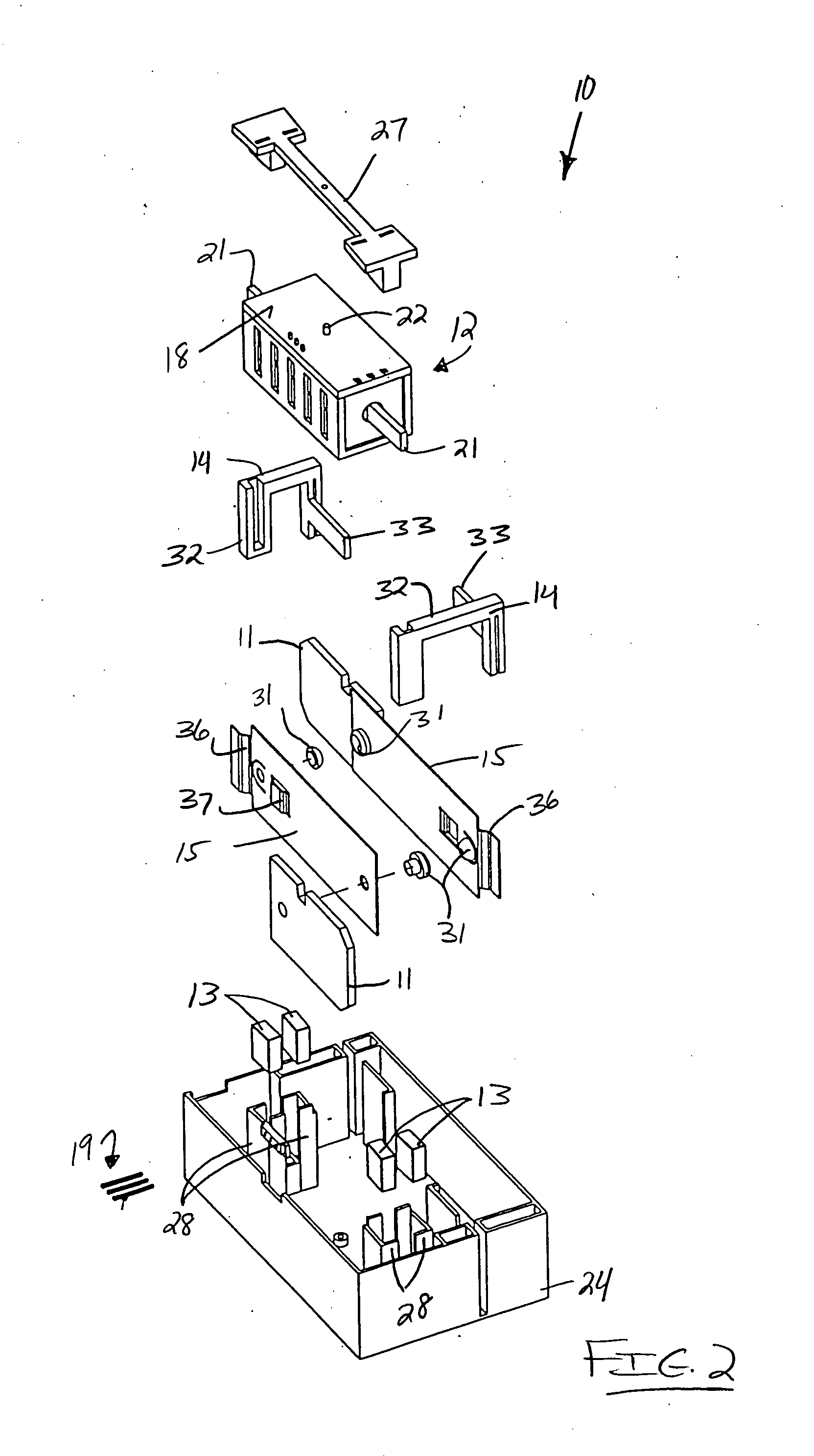
[0050]Referring now to the drawings, the preferred embodiment of the present invention concerns a so-called bi-stable electromagnetic relay (with X-drive motor) assembly 10 as generally illustrated and referenced in FIGS. 1, 2, 4, and 5. Assembly 10 is believed to teach the basic structural concepts supporting the present invention, which basic structural concepts may be applied to either single pole assemblies as generally depicted and supported by assembly 10, or multiple pole assemblies. In this last regard, an exemplary four-pole assembly 20 is generally illustrated and referenced in FIGS. 16-19.

[0051]The electromagnetic relay assembly 10 essentially functions to selectively enable current to pass through switch termini 11. The electromagnetic relay assembly 10 preferably comprises an electromagnetic coil assembly 12, first and second pairs of opposed permanent magnets 13, and a switch assembly comprising various components, including first and second linkage arms 14 (comprising...


PUM


Abstract

An electromagnetic relay assembly comprises a rotatable electromagnetic coil assembly, first and second pairs of opposed permanent magnets, and a switch assembly. The coil assembly comprises a coil, a core, and a rotatable coil housing. The coil is wound around the core. The core comprises opposed core termini, and the coil housing has an axis of rotation orthogonal to the coil axis. The magnet pairs fixedly positioned adjacent the core termini such that the core termini are respectively displacable intermediate the magnet pairs. The coil operates to create a magnetic field directable through the core for imparting coil housing rotation about the axis of rotation via attraction to the positioned / anchored magnets. The core termini displace linkage arms, and the linkage arms actuate contact-spring assemblies of the switch assembly intermediate open and closed positions.

Description

BACKGROUND OF THE INVENTION[0001]1. Field of the Invention[0002]The disclosed invention generally relates to an electromagnetic relay assembly incorporating a rotatable coil-core assembly. More particularly, the disclosed invention relates to an electromagnetic relay assembly having a magnetically actuable coil assembly rotatable about an axis of rotation extending orthogonally relative to the coil assembly axis.[0003]2. Brief Description of the Prior Art[0004]Generally, the function of an electromagnetic relay is to use a small amount of power in the electromagnet to move an armature that is able to switch a much larger amount of power. By way of example, the relay designer may want the electromagnet to energize using 5 volts and 50 milliamps (250 milliwatts), while the armature can support 120 volts at 2 amps (240 watts). Relays are quite common in home appliances where there is an electronic control turning on (or off) some application device such as a motor or a light. Several e...

Claims


Application Information

Patent Timeline
Patent Type & Authority Applications(United States)
IPC IPC(8): H01H45/00
CPCH01H1/50H01H1/54H01H50/44H01H51/2263H01H50/641H01H51/2272H01H50/305H01H50/54H01H51/22
Inventor GRUNER, PHILIPP
Owner HONGFA HLDG U S
Learn More