
Horizontal flanging die mechanism

A flanging mold, horizontal technology, applied in the direction of forming tools, manufacturing tools, feeding devices, etc., can solve the problems of increasing the mold process, occupying a large space for the mechanism, and increasing the difficulty of mold matching and debugging, so as to simplify the stamping process and improve work efficiency effect

Active Publication Date: 2020-07-24
BAIC GRP ORV CO LTD
View PDF11 Cites 0 Cited by
  • Summary
  • Abstract
  • Description
  • Claims
  • Application Information

AI Technical Summary

Problems solved by technology

The mold structure using this process is complex, and the mechanism takes up a large space; it usually conflicts with other process content during part processing, thereby increasing the mold process; or it is necessary to adjust the stamping direction of the workpiece, which increases the difficulty of mold coordination and debugging, resulting in increased manufacturing costs.
And this process does not solve all types of side flanging of parts

Method used


Image

  • Horizontal flanging die mechanism
  • Horizontal flanging die mechanism
  • Horizontal flanging die mechanism

Examples


Embodiment Construction

[0055] In order to make the purpose, technical solutions and advantages of the embodiments of the present invention more clear, the following will clearly and completely describe the technical solutions of the embodiments of the present invention in conjunction with the drawings of the embodiments of the present invention. Apparently, the described embodiments are some, not all, embodiments of the present invention. All other embodiments obtained by those skilled in the art based on the described embodiments of the present invention belong to the protection scope of the present invention.

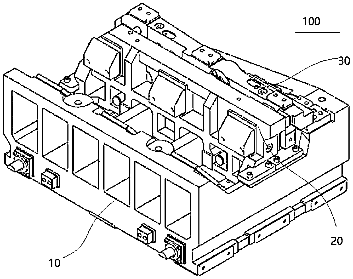
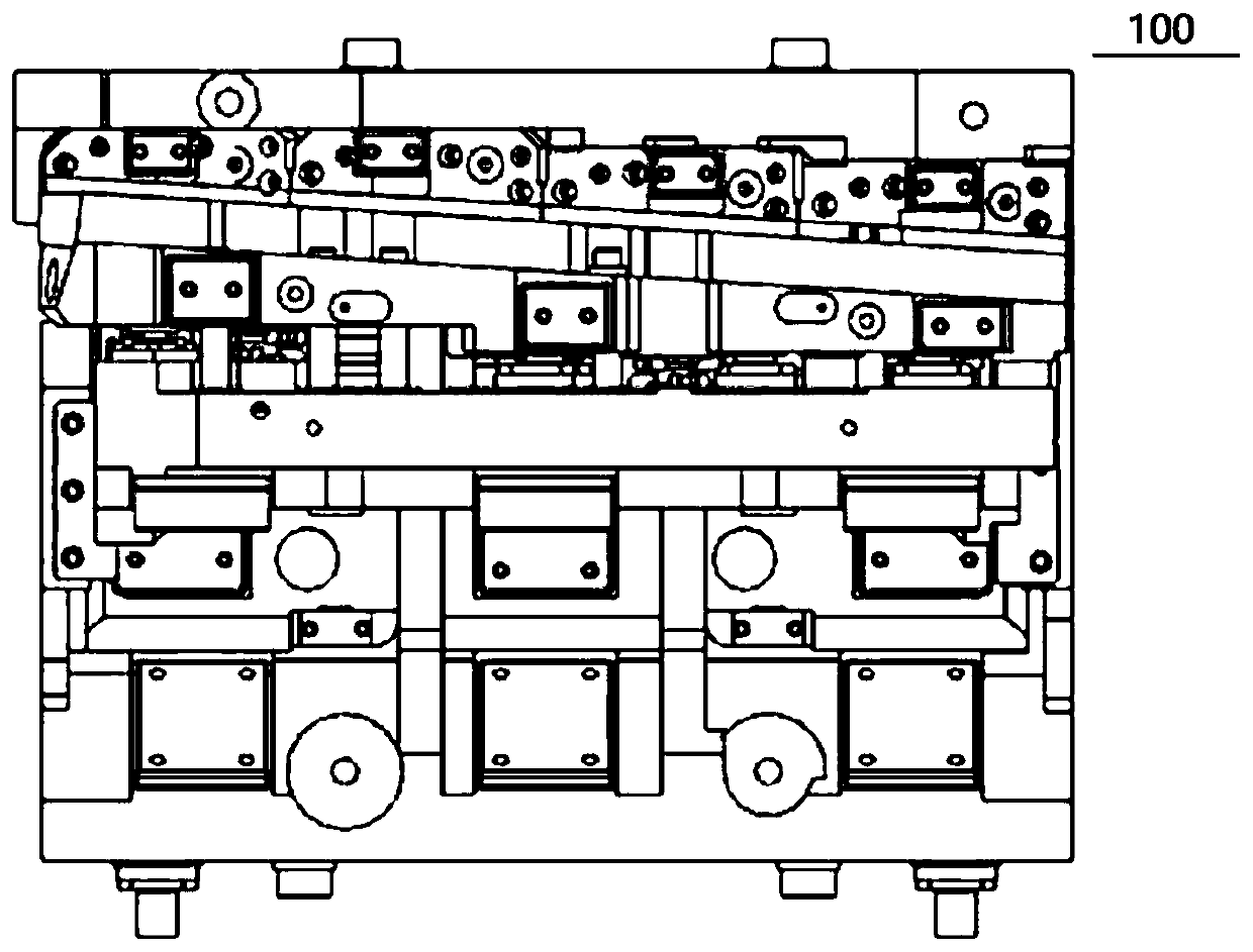
[0056] Firstly, the horizontal flanging mold mechanism 100 according to the embodiment of the present invention will be described in detail with reference to the accompanying drawings.

[0057] The horizontal flanging mold mechanism 100 according to the embodiment of the present invention includes a pulley mechanism 10 , a retreat mechanism 20 and a side pressing core assembly 30 .

[0058...


PUM


Abstract

The invention provides a horizontal flanging die mechanism. The mechanism comprises a pulley mechanism, a rollback mechanism and a side material pressing core assembly, wherein one end of the upper surface of the pulley mechanism is provided with a flanging insert, and a mounting part and a sliding part are defined in the pulley mechanism; the rollback mechanism is arranged in the sliding part ina sliding mode; the side material pressing core assembly is arranged in the mounting part, and a male die cutting edge is arranged below one side of the side material pressing core assembly. Accordingto the horizontal flanging die mechanism, in the whole flanging process, the pulley mechanism, the rollback mechanism and the side material pressing core assembly jointly complete feeding and returning actions, the male die cutting edge is machined below one side of the side material pressing core assembly and functions as material pressing and a male die, the pulley mechanism drives the flanginginsert to move in the horizontal direction far away from a fixed male die, and a flanging area of a workpiece is horizontally flanged from inside to outside. The horizontal flanging die mechanism simplifies the stamping process and improves the working efficiency.

Description

technical field [0001] The invention relates to the technical field of vehicle processing, in particular to a horizontal flanging mold mechanism. Background technique [0002] With the rapid development of the automobile industry, the shape and characteristics of body panels tend to be complex, and the related stamping dies need technological innovation to meet product design requirements and ensure part quality. In the development of automotive panel molds, because some parts have flanging features at a negative angle to the stamping direction, a side flanging process is required. In the prior art, the side flanging process of self-made parts from the outside to the inside is usually adopted, and the pressing core and the flanging punch are independent structures; the flanging punch and the flanging insert are installed on different sliders There is no relative motion relationship. The mold structure using this process is complex, and the mechanism takes up a lot of space...

Claims


Application Information

Patent Timeline
Patent Type & Authority Applications(China)
IPC IPC(8): B21D19/08B21D37/10B21D43/00
CPCB21D19/08B21D37/10B21D43/003
Inventor 王冲张学文李丹彤于宁
Owner BAIC GRP ORV CO LTD
Learn More