
Method of manufacturing and refinishing integrally bladed rotors

a manufacturing method and technology for integral bladed rotors, applied in the direction of engine fuction, maintenance and safety accessories, milling equipment, etc., can solve the problems of insufficient precision of integral bladed rotors, insufficient smoothness of blades, and insufficient precision of blades to be ready for use, so as to improve the finish, remove excess material, and accurately shape blades and flow channels

Active Publication Date: 2010-03-25
MTU AERO ENGINES GMBH
View PDF19 Cites 21 Cited by
  • Summary
  • Abstract
  • Description
  • Claims
  • Application Information

AI Technical Summary

Benefits of technology

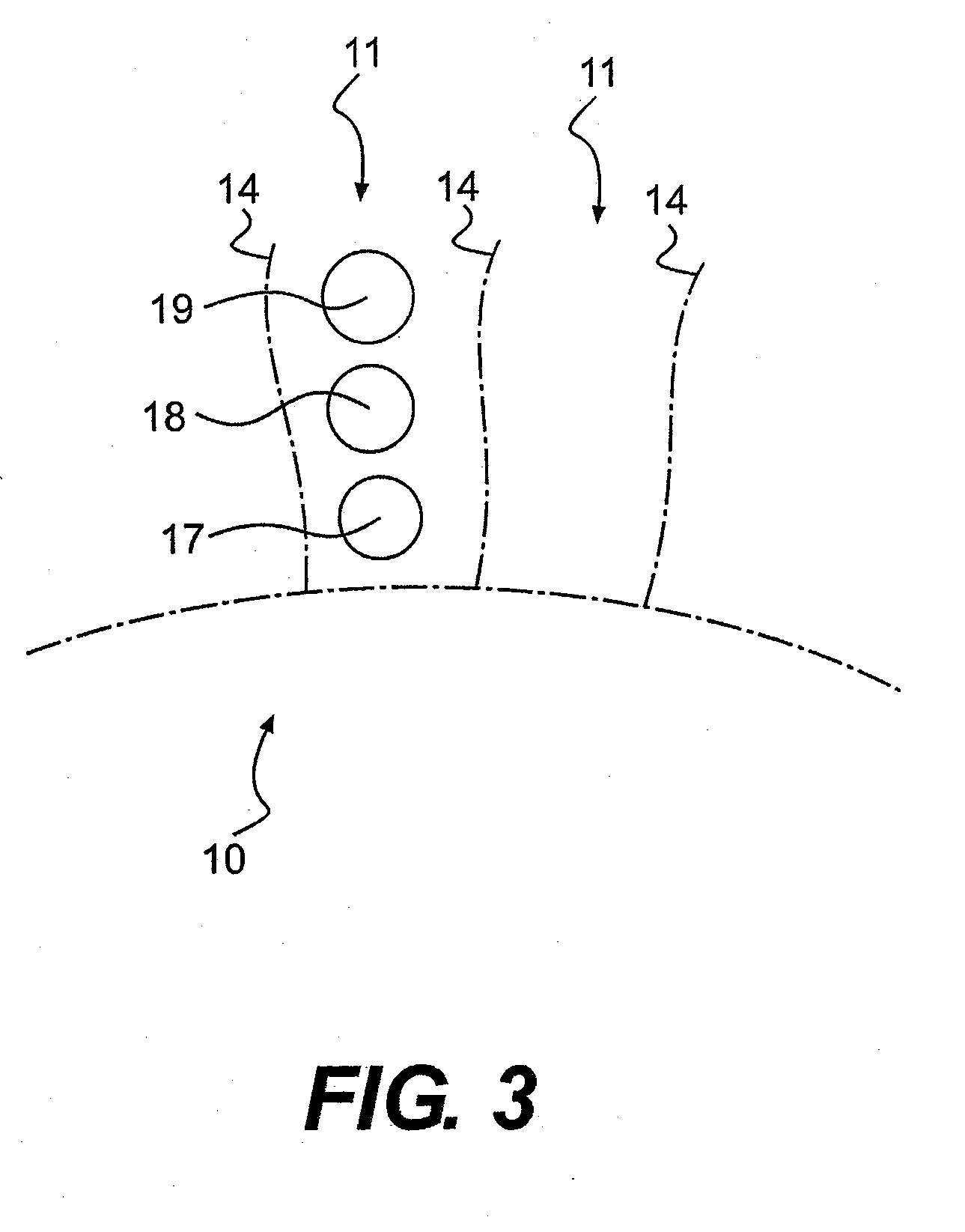
[0005]Material in the region of the flow channels is initially removed, according to an exemplary embodiment of the invention, by a drilling process. After the drilling process is completed, the removal of material in the region of the flow channels continues with an initial milling process, which more accurately defines the shape of the blade surfaces. These two initial drilling and milling steps are similar to the steps described in U.S. Pat. No. 7,225,539, which is hereby incorporated by reference in its entirety. The combination of a drilling process followed by a milling process for material removal reduces significantly the manufacturing time and results in a less expensive manufacturing of the IBR's than other manufacturing processes. However, after these steps the blades are still not sufficiently smooth and their shape is not sufficiently accurate to be ready for use.
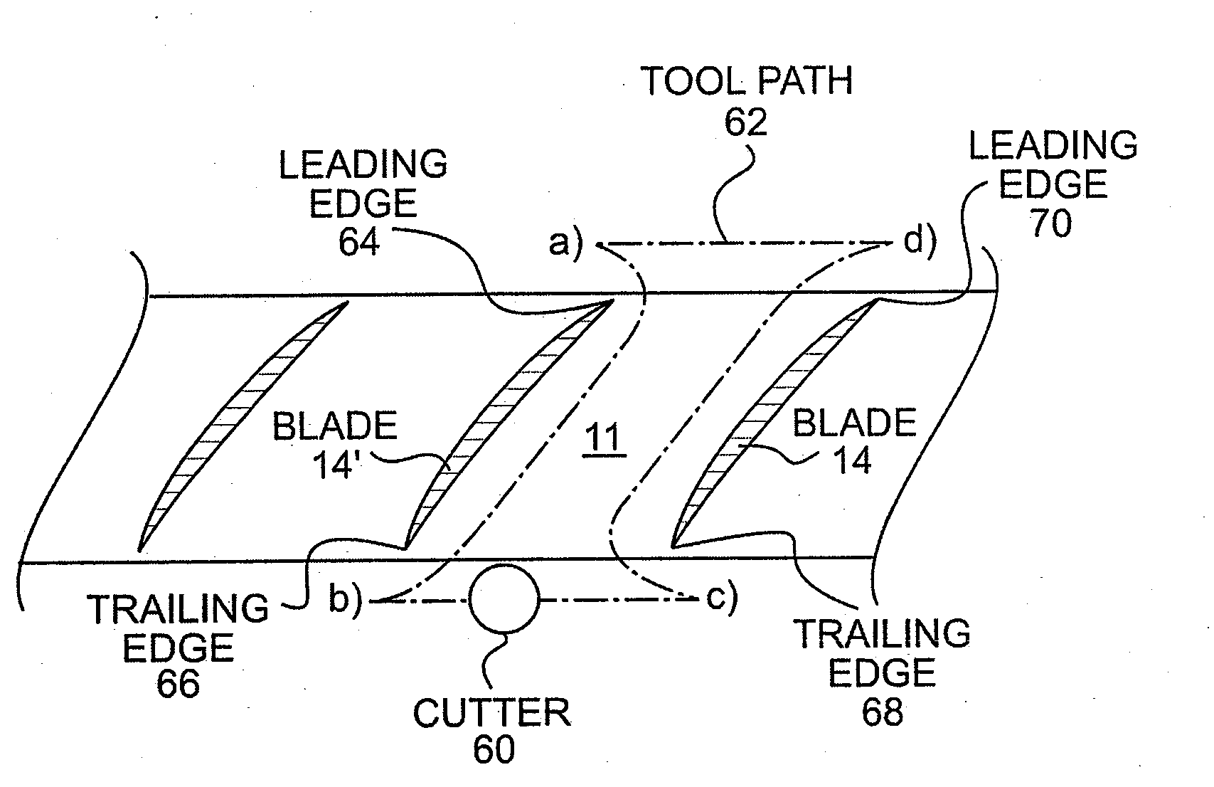
[0011]In one exemplary embodiment, the initial milling step is carried out along an axis of the milling tool or cutter that is generally perpendicular to the center line approximating the center of the flow channel being manufactured. For example, the milling tool may operate along a generally radial axis, so that it extends from the tip towards the root of the blades. The milling tool may be moved along the concave and the convex surfaces of each blade, and around the leading edge and trailing edge thereof, to remove excess material and more accurately shape the blades and the flow channel.
[0012]Because the initial milling step does not produce blades that are ready for use, an additional step is carried out, according to exemplary embodiments of the invention, to produce a better finish and a more accurate shape for the blades. For example, mismatches, waviness and chatter due to the flow-wise drilling and initial milling sequence may be removed or reduces by the additional finishing milling step. This additional automated step removes the need to manually finish the blades after the initial drilling and milling steps, and also increases the accuracy and quality of the finish. According to exemplary embodiments of the invention, the additional step may be an I-flow milling process, in which the finishing milling step is carried out after a damping material is used to fill all the flow passages between the blades.
[0013]Prior to the finishing milling step, the rough shape of the blades and of the flow passages are already defined. A damping material is then inserted in the flow passages, between adjacent pairs of blades, to completely surround each of the compressor or turbine blades. This material, for example, may dampen vibrations of the blades during machining. The milling cutter tool is then used to refinish the blade surface, removing both the damping material and the blade material to produce a smooth and accurate shape of the blade surfaces.
[0014]In one exemplary embodiment, the milling tool is moved along one surface of a first blade defining the flow path, then across the flow path and along the opposite surface of the adjacent blade. The milling procedure may start at the leading edge, concave side of a blade, travel along the concave surface of the blade to the trailing edge, move across to flow passage to the convex side of the adjacent blade, and then travel to its leading edge along the convex surface. The opposite routing of the milling tool may also be used to obtain substantially the same results. The milling tool may be moved as explained above to ensure that for each blade, at least one surface is milled while the opposite surface is still encased in the damping material, to reduce or prevent vibration and deflection of the blade that may result in an inadequate blade finish. According to embodiments of the invention, the path of the milling tool is selected to maximize the damping effect of the damping material, by delaying the removal of the material from one side of the blade while the other side is being finished. Thus, to maximize the damping effect, the finishing milling tool may move along a path that preferentially mills one surface of a blade while the other surface of the same blade is in contact with the damping material.

Problems solved by technology

Conventional manufacturing methods for IBR's tend to be difficult and time consuming to carry out, and often require manual finishing steps, resulting in an expensive manufacturing process for integrally bladed rotors.
However, after these steps the blades are still not sufficiently smooth and their shape is not sufficiently accurate to be ready for use.
The blade resulting after this initial or coarse milling step is still rough, and does not have a sufficiently accurate shape and sufficiently smooth surface to be used in the turbine engine.
This material, for example, may dampen vibrations of the blades during machining.

Method used


Image

  • Method of manufacturing and refinishing integrally bladed rotors
  • Method of manufacturing and refinishing integrally bladed rotors
  • Method of manufacturing and refinishing integrally bladed rotors

Examples


Embodiment Construction

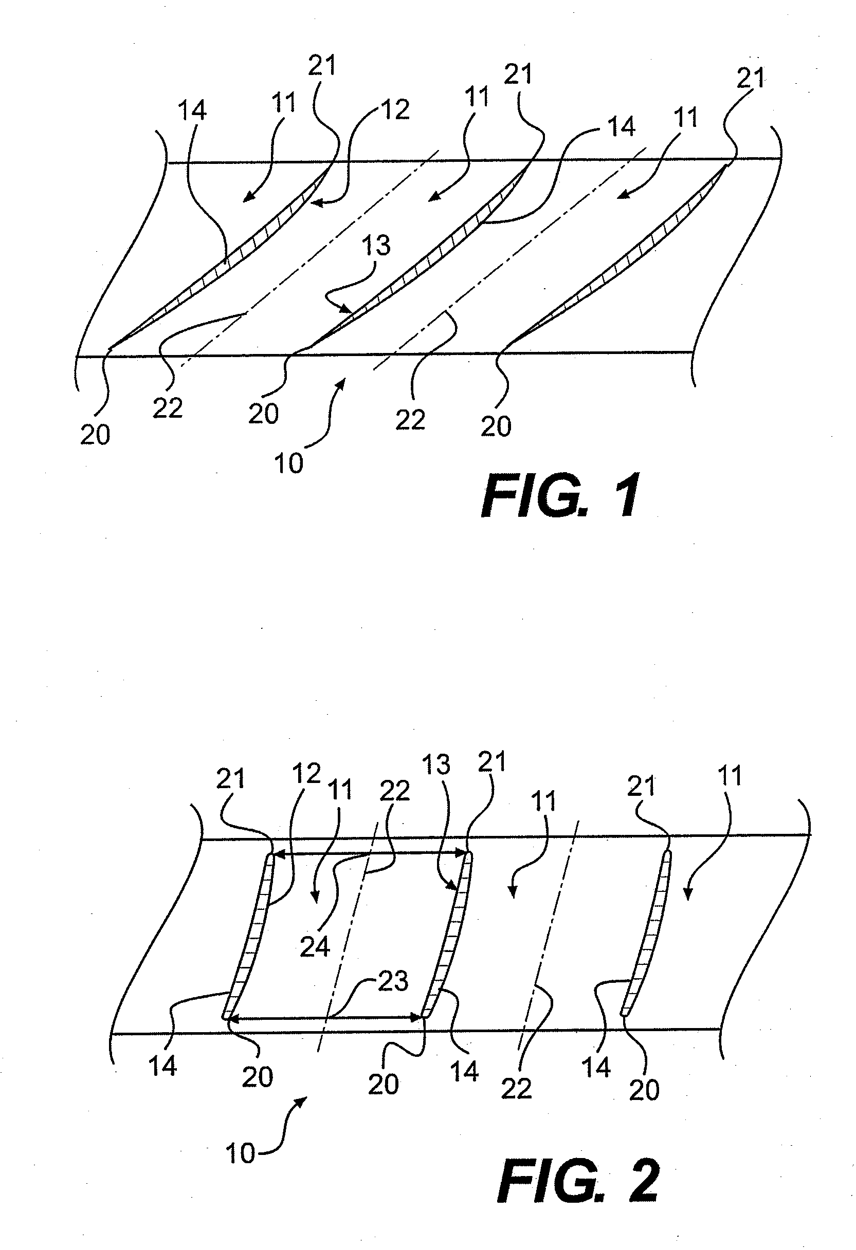
[0022]FIGS. 1 and 2 show a radial cross sectional view of an exemplary component of a gas turbine which is manufactured as an integrally bladed rotor 10. According to the present invention, a method is provided for manufacturing such an integrally bladed rotor 10, that is formed of materials that are difficult-to-cut and to machine, such as, for example, nickel alloys or titanium alloys. These materials are typically used in the manufacture of compressor and turbine blades of gas turbines, particularly for aircraft propulsion applications. However, other applications for the machining methods according to the invention may also be envisioned, in which components with complex shapes have to be manufactured from materials that are difficult to machine.

[0023]The exemplary integrally bladed rotor 10 is manufactured by initially forming recesses 11 between two opposite sidewalls 12, 13, in a workpiece block. The two opposite side-walls 12, 13 form opposing surfaces of two adjacent blades...


PUM

PropertyMeasurementUnit
dampingaaaaaaaaaa
shapesaaaaaaaaaa
shapeaaaaaaaaaa

Abstract

A method of forming integrally bladed rotors for gas turbines is described. The method includes drilling in a workpiece material recesses defining flow passages and rotor blades, performing a coarse milling step to refine surfaces of the rotor blades, and filling the recesses between the rotor blades with a damping material, thus encasing the rotor blades in the damping material. The method further includes performing a finishing milling step to remove the damping material and the workpiece material on surfaces of the rotor blades, while maximizing a damping effect of the damping material on the rotor blades. To maximize the damping effect, the finishing milling tool moves along a path that preferentially mills one surface of a blade while the other surface is in contact with the damping material.

Description

FIELD OF THE INVENTION[0001]The present invention relates to a method for the manufacture of machinery components made of difficult-to-cut materials, especially requiring accurate adherence to complex shapes and surface finishing. More specifically, the invention relates to manufacturing integrally bladed rotors for gas turbines, by forming in a block of material multiple recesses defining flow passages, each of the recesses having side walls, the side walls defining surfaces of the blades.BACKGROUND AND SUMMARY OF THE INVENTION[0002]Integrally bladed rotors (IBR's) for gas turbines are often called “blisks” or “blings”, depending on the cross-sectional shape of the rotor. A disk-shaped rotor having integrated blades is called “blisk” (bladed disk), a ring-shaped rotor having integrated blades is called “bling” (bladed ring). IBR's are formed from a single piece of material that includes the hub, the disk and all the rotor blades, in contrast to conventional rotors in which multiple...

Claims


Application Information

Patent Timeline
Patent Type & Authority Applications(United States)
IPC IPC(8): B23Q11/00B23P15/04
CPCB23C3/18Y10T29/4981B23C2240/21B23C2250/16B23P15/006F01D5/26F01D5/34F05D2260/96F05D2230/50F05D2230/10Y10T29/49336Y10T29/49325Y10T29/4932Y10T29/49812Y10T29/49996Y10T409/304312B23C2215/44
Inventor ROZIC, MARJANNOWAK, DARIUSZWASZCZUK, DEREK
Owner MTU AERO ENGINES GMBH
Learn More