
Multi-focus optical-resolution photoacoustic microscopy with ultrasonic array detection

a photoacoustic microscopy and ultrasonic array technology, applied in the field of multi-focus optical-resolution photoacoustic microscopy with ultrasonic array detection, can solve the problems of insensitive techniques to optical absorption, low detection efficiency, and low detection efficiency of ultrasonic arrays

Active Publication Date: 2012-08-16
CALIFORNIA INST OF TECH
View PDF4 Cites 41 Cited by
  • Summary
  • Abstract
  • Description
  • Claims
  • Application Information

AI Technical Summary

Problems solved by technology

However, these techniques are insensitive to optical absorption that is related to important biochemical information.
Other well-known techniques, such as confocal microscopy and multi-photon microscopy, often involve the introduction of exogenous dyes, which, with a few notable exceptions, have relatively high toxicity.
In addition, acoustic microscopic imaging and spectroscopy systems are sensitive to acoustic impedance variations only, which have low contrast for early-stage cancer and provide little functional information about biological tissue except flow.

Method used


Image

  • Multi-focus optical-resolution photoacoustic microscopy with ultrasonic array detection
  • Multi-focus optical-resolution photoacoustic microscopy with ultrasonic array detection
  • Multi-focus optical-resolution photoacoustic microscopy with ultrasonic array detection

Examples


Embodiment Construction

[0021]While the making and using of various embodiments of the present disclosure are discussed in detail below, it should be appreciated that the present disclosure provides many applicable inventive concepts that can be embodied in a wide variety of specific contexts. The specific embodiments discussed herein are merely illustrative of specific ways to make and use the disclosure and do not delimit the scope of the disclosure.

[0022]To facilitate the understanding of this disclosure, a number of terms are defined below. Terms defined herein have meanings as commonly understood by a person of ordinary skill in the areas relevant to the present disclosure. Terms such as “a,”“an” and “the” are not intended to refer to only a singular entity, but include the general class of which a specific example may be used for illustration. The terminology herein is used to describe specific embodiments of the disclosure, but their usage does not delimit the disclosure, except as outlined in the c...


PUM

PropertyMeasurementUnit
diameteraaaaaaaaaa
photoacoustic microscopyaaaaaaaaaa
optical coherence tomographyaaaaaaaaaa

Abstract

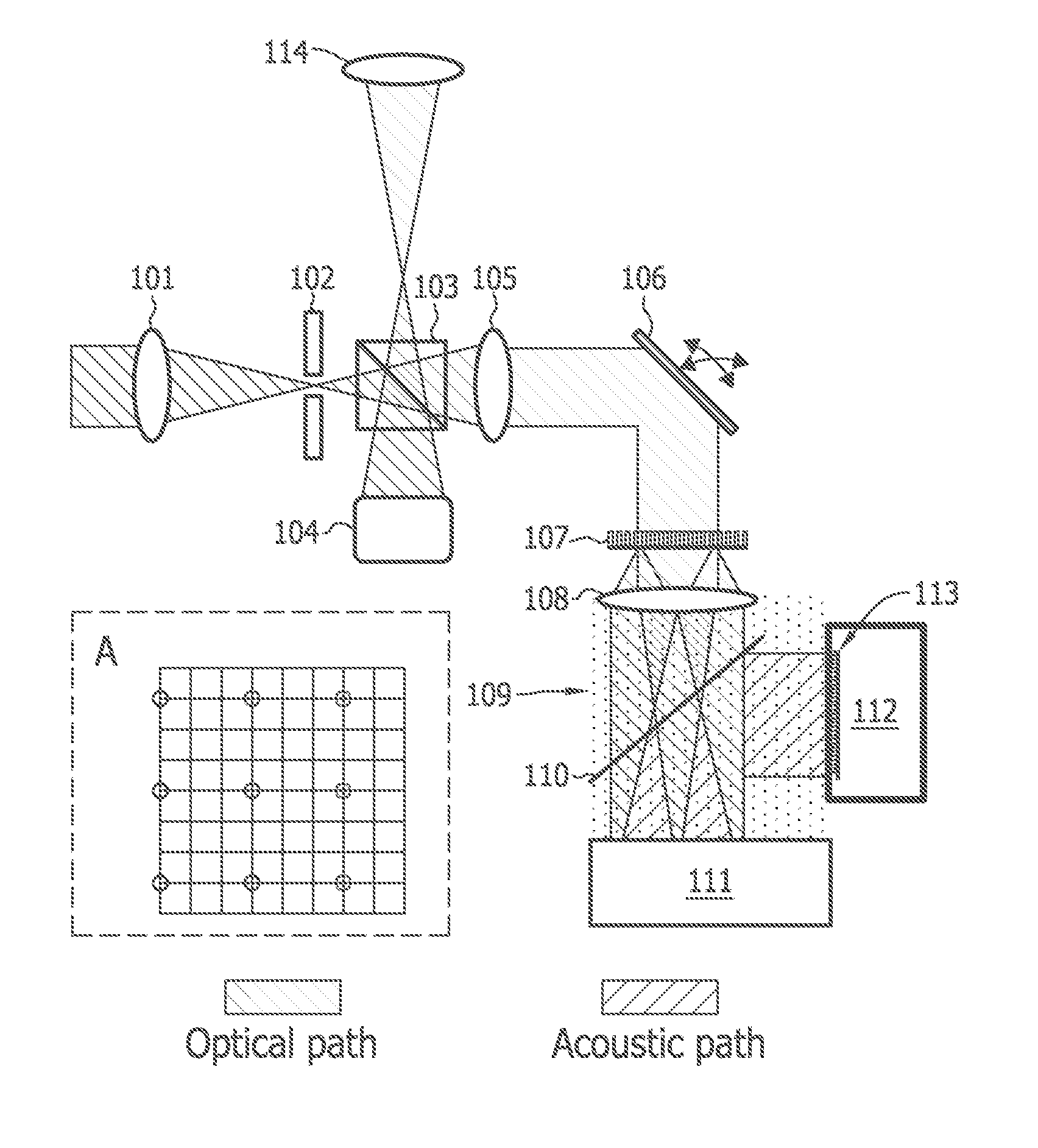
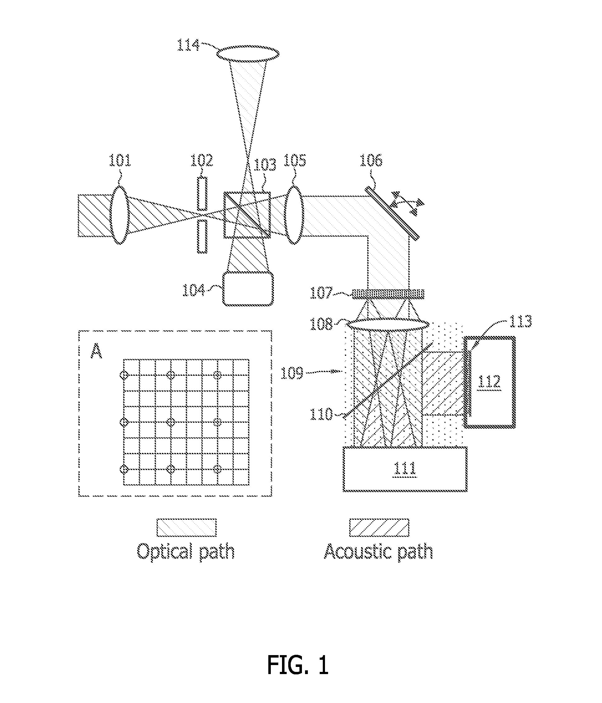
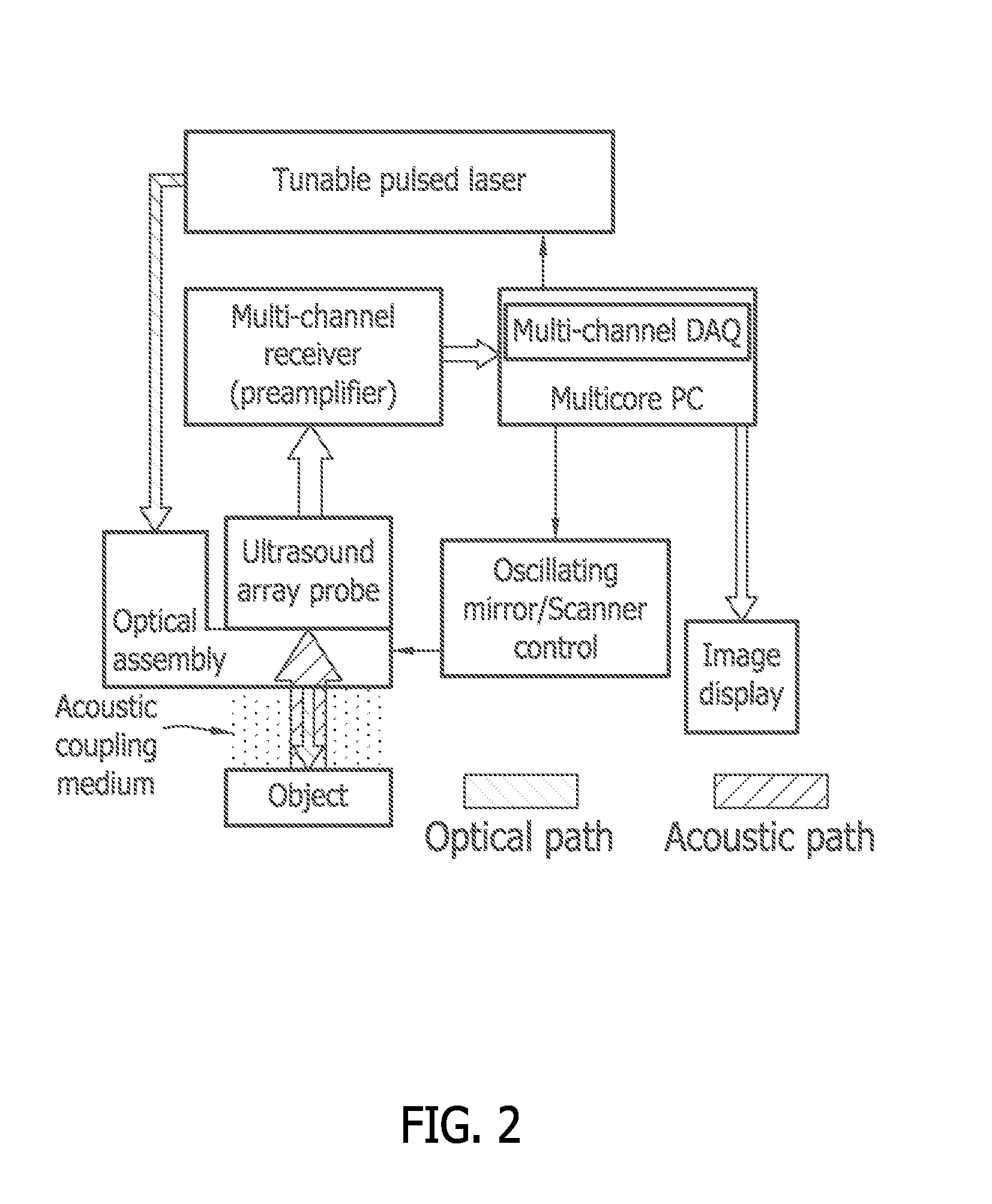
A probe for use with an imaging system, including a scanning device configured to receive a first light beam from a light source, a beam-divider configured to split the first light beam into a plurality of second light beams, and a focusing device configured to focus each of the second light beams on respective locations in an object of interest.

Description

CROSS-REFERENCE TO RELATED APPLICATION[0001]This application claims the benefit of U.S. Provisional Application No. 61 / 442,148 filed Feb. 11, 2011, which is incorporated herein in its entirety.STATEMENT REGARDING FEDERALLY SPONSORED RESEARCH & DEVELOPMENT[0002]This invention was made with government support under grants R01 EB000712 and U54 CA136398, both awarded by the U.S. National Institutes of Health. The government has certain rights in the invention.BACKGROUND[0003]The ability to image microstructures, such as the micro-vascular network in the skin, the GI tract, or the brain cortex, and to monitor physiological functions of tissue is invaluable. One of the promising technologies for accomplishing this objective is photoacoustic microscopy. Current high-resolution optical imaging techniques, such as optical coherence tomography, can image up to approximately one transport mean free path (about 1 mm) into biological tissue. However, these techniques are insensitive to optical a...

Claims


Application Information

Patent Timeline
Patent Type & Authority Applications(United States)
IPC IPC(8): G01N29/24G02F1/29G02F1/33G02B27/10G02B26/10
CPCA61B5/0095A61B5/4064G02B26/105A61B5/441A61B5/42G01N29/2418G01N2291/028G01N2291/106G02B21/36
Inventor WANG, LIHONGSONG, LIANGMASLOV, KONSTANTINRAO, BIN
Owner CALIFORNIA INST OF TECH
Learn More