Robot for cleaning and inspection of conduits and its control unit

a technology for conduits and robots, applied in the direction of cleaning process and equipment, pipe elements, hollow article cleaning, etc., can solve the problems of negative health, virtually impossible manual cleaning, and impact on its use, so as to facilitate the control of the robot and the operator's convenien

Active Publication Date: 2012-08-02
JETTYROBOT SRO +1
View PDF12 Cites 53 Cited by
  • Summary
  • Abstract
  • Description
  • Claims
  • Application Information

AI Technical Summary

Benefits of technology

[0024]A great advantage is when the plane passing through the second and third pin axes and the plane passing through the third and fourth pin axes are perpendicular to each other because when the rod is sufficiently long or the second pin is placed in the carriage in a manner allowing movement perpendicular to the robot axis, the normal force applied by the driving unit to the conduit wall is then directly proportional to the air pressure in the pneumatic actuator.
[0027]Another possible alternative is that the body contains a sensor of synchronizing mechanism position, which is attached to this body and to the carriage and it is interconnected with a monitor displaying measured value. Position sensor allows to find out that the robot enters into conduit with smaller diameter and more importantly it allows to detect situation when the robot axis is not parallel with the conduit axis.
[0028]Another possible alternative is that the body contains an inclinometer, which is attached to this body and it is interconnected with a monitor displaying measured values. Inclinometer allows to inform the operator about the robot orientation in the conduit and makes control of the robot easier for the operator.
[0029]Another possible alternative is that the body contains a gyroscope, which is attached to this body and it is interconnected with a monitor displaying measured values. Gyroscope informs the operator about the robot orientation in the conduit and makes control of the robot easier for the operator.
[0033]Proposed solution presents a robotic system able to travel inside air conduits and similar, especially with large diameter, turn in their bends and pass branches. The robot is able to travel inside horizontal, sloped as well as vertical conduits. The robot is able to drag a hose of great weight. The robot is equipped with a camera and applicator of mixture. Mixture may include pressurized air, high-pressure water and / or a stream of dry ice particles within a stream of pressurized air. Design of the robot keeps the robot body centralized in the conduit. Applicator centralized in this way achieves the best parameters of cleaning.

Problems solved by technology

Ventilating, air-conditioning, and exhausting conduits suffer by deposition of dirt on the inner walls, which could have negative health (e.g. legionella type bacteria), fire (e.g. flammable deposits), or functional (narrowing cross section) impacts on its use.
Small diameter of some such conduits makes manual cleaning virtually impossible.
U.S. Pat. No. 6,026,538 suggests to whirl deposited dirt by air blast or by brush but it does not solve the way how to remove firmly attached dirt.
For removing firmly attached deposits, solid fats and oils, asphalts, or baked dirt brushing is unsuitable.
Water blasting is unsuitable for most of the air ducts as the water would flood the space or technological equipment located beneath the duct.
In order to centralize a robot in the duct U.S. Pat. No. 5,113,885 and CN1962091 propose to use a spring, which however does not guarantee constant normal force to the wall for different conduit diameters.
Due to rather varied obstacles in the conduit this principle of drive cannot be used in air conduits.
In addition, this method cannot be adapted for conduits with rectangular cross section.
For this method however it is difficult to handle conduits bends and branching.
Existing solutions are either not capable of dragging longer sections of heavy hoses, working in large and varying diameter conduits, passing the conduit bends and branches, or they are not able to automatically center the cleaning medium nozzle or to resist radial forces caused by the flowing medium.
No system was able to satisfy all these requirements simultaneously, while partial solutions of these problems contradicted each other.
Another setback of all solutions known so far is complex control of multiple driving units when passing bends since the operator is not able to control multiple parameters in real time at once.
Next source of problems is possible slippage of tracks because the conduit surface has various value of friction coefficient and depends on the type of deposited dirt.
Where multiple tracks are used while each track should have different speed, direct control is impossible because the operator is not able to control multiple tracks at the same time.

Method used


Image

  • Robot for cleaning and inspection of conduits and its control unit
  • Robot for cleaning and inspection of conduits and its control unit
  • Robot for cleaning and inspection of conduits and its control unit

Examples


Embodiment Construction

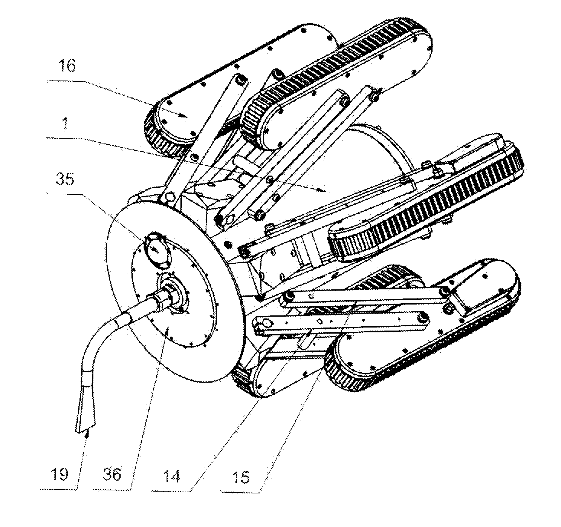
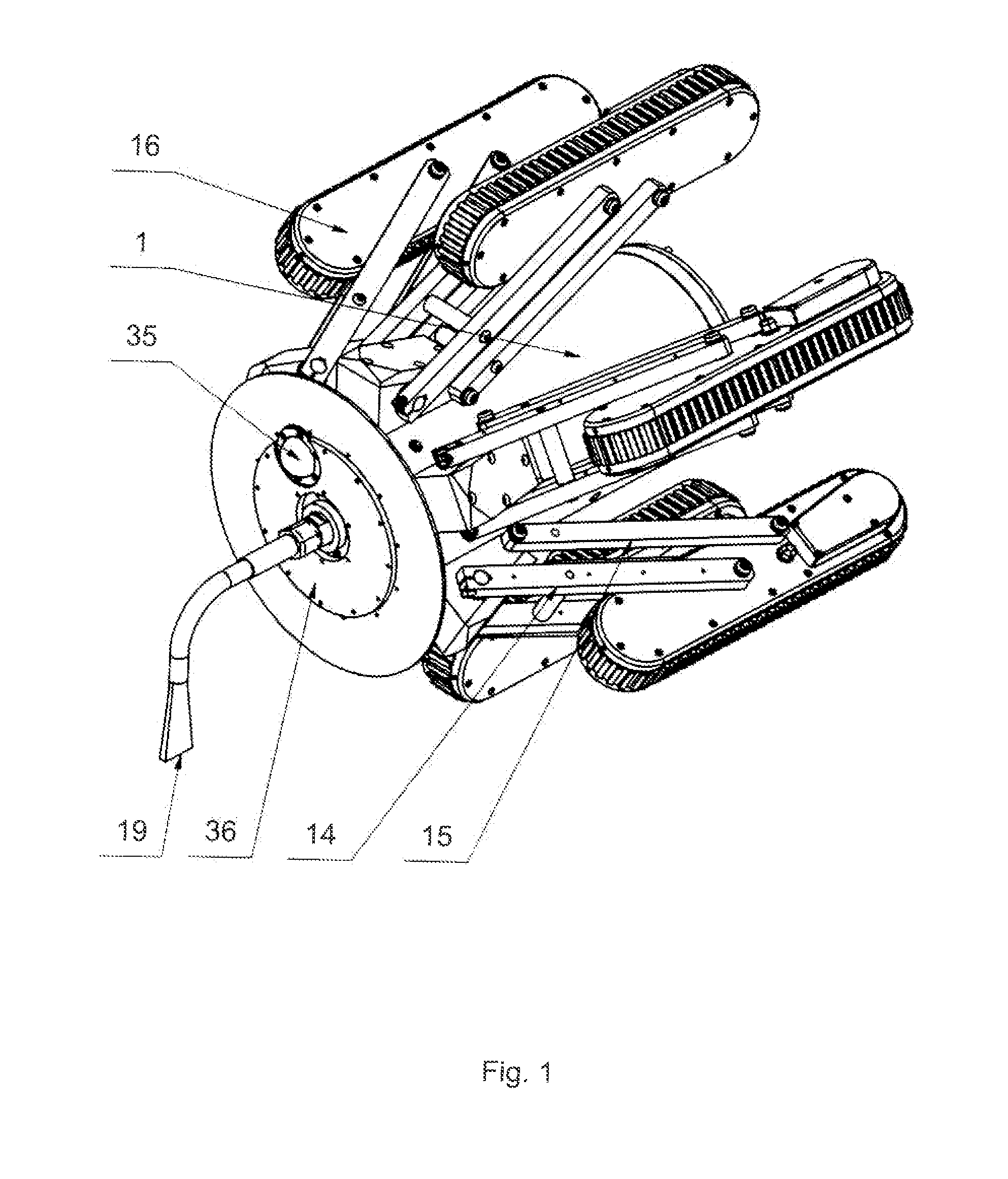
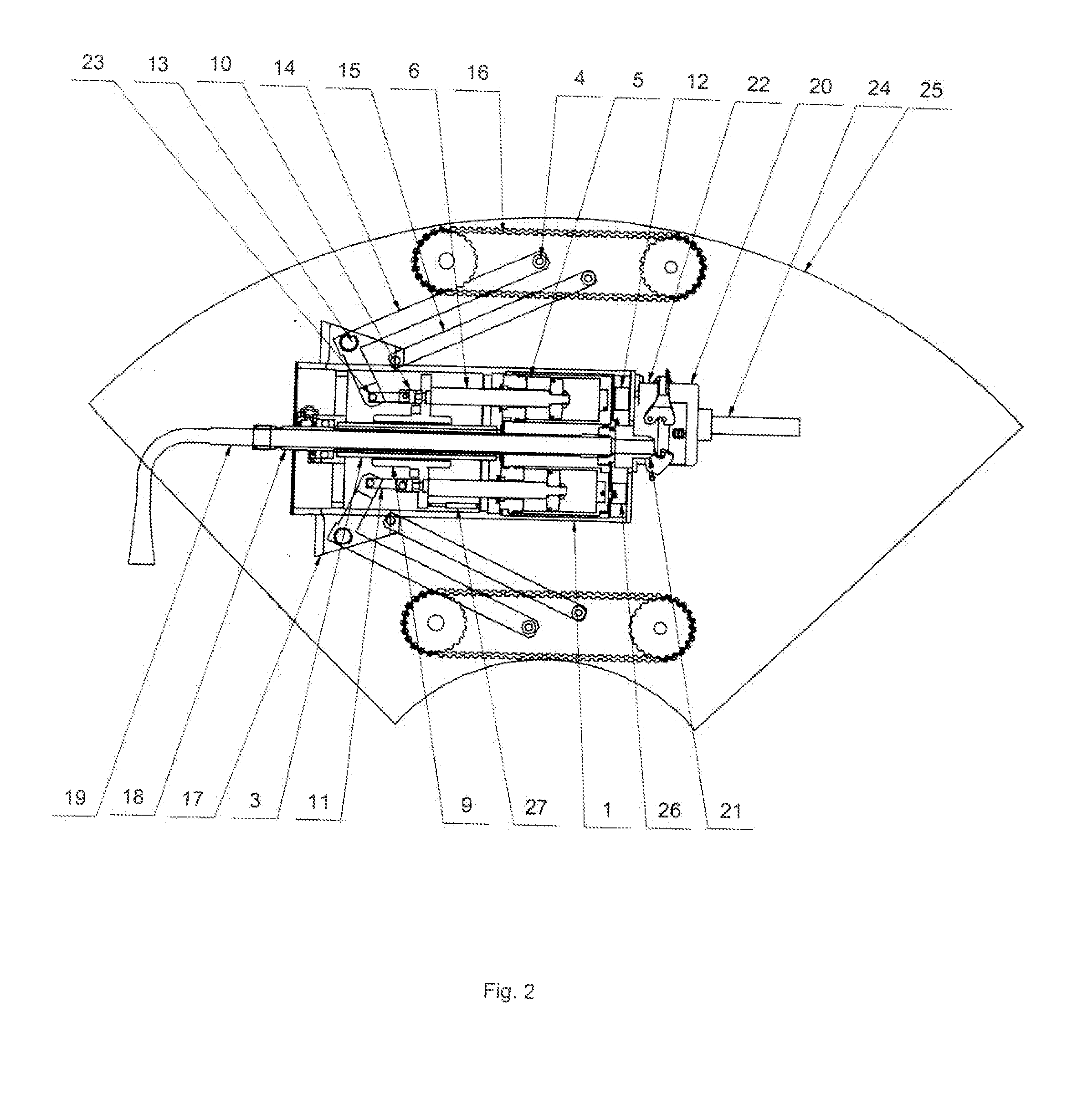
[0042]Robot for cleaning and inspection of conduits according to the presented solution, FIG. 1, 2, 4, consists of the body 1, which accommodates a hose 18 with cleaning medium, to which a nozzle 19 for cleaning medium is attached. On the front side of the body 1 are installed a headlight 36 and a video camera 35 in a way common to this type of devices. Hose 18 of the cleaning medium here passes through axis of the body 1, to which are radial-symmetrically attached minimum three driving units 16 with tracks or wheels. The robot 111 is equipped with a synchronizing mechanism formed by a rectilinear prismatic joint placed inside the body 1. This rectilinear prismatic joint consists of a guiding device 3 of the synchronizing mechanism attached to the body 1. On the guiding device 3 is placed a carriage 9, which is sliding in direction of the longitudinal axis of the body 1. Driving units 16 are attached to the carriage 9 symmetrically via identical mechanisms forming prismatic joints. ...


PUM


Abstract

A robot for cleaning and inspecting conduits has a synchronizing mechanism, which extends all driving units simultaneously and with a constant normal force applied to the conduit wall. The robot may be equipped with adapters for conduits with rectangular cross section, and with extension bars for conduits with large diameters. Further, the robot may be equipped with sensors monitoring the robot status, these include a sensor of the synchronizing mechanism position, inclinometer and gyroscope. Data from these sensors may be displayed on a monitor. The movement of the robot inside the conduit and therefore the speed of individual tracks is controlled by the operator by three control elements: direction of turning, diameter of bend and speed of motion. The robot is also able to travel backwards inside the conduit automatically based on stored information about forward movement.

Description

BACKGROUND OF THE INVENTION[0001]The invention deals with technical solution of a robot for cleaning and inspection of conduits and its control unit.DESCRIPTION OF PRIOR ART[0002]Ventilating, air-conditioning, and exhausting conduits suffer by deposition of dirt on the inner walls, which could have negative health (e.g. legionella type bacteria), fire (e.g. flammable deposits), or functional (narrowing cross section) impacts on its use. Presence of deposits above certain level is solved either by replacement of the conduit, or by cleaning of its inner surface. Small diameter of some such conduits makes manual cleaning virtually impossible.[0003]Several technologies dealing with robotic cleaning of conduits exist (U.S. Pat. No. 6,026,538). One of them is brushing of inner surface (U.S. Pat. No. 5,528,789, CN101069890).[0004]U.S. Pat. No. 6,026,538 suggests to whirl deposited dirt by air blast or by brush but it does not solve the way how to remove firmly attached dirt. Similarly, U.S...

Claims


Application Information

Patent Timeline
IPC IPC(8): G06F19/00
CPCB08B9/049B62D55/084B62D55/065B08B9/0495F16L2101/30F16L55/26B08B9/04B08B9/0497
Inventor FARKAVEC, PETRSMUTNVLADIMIR
Owner JETTYROBOT SRO
Why Eureka
Try Eureka